7-14
Component Access / Removal
Built-In
Built-In
(600-
(600-
2
2
)
)
Series
Series
#3758407 - Revision B - August, 2006
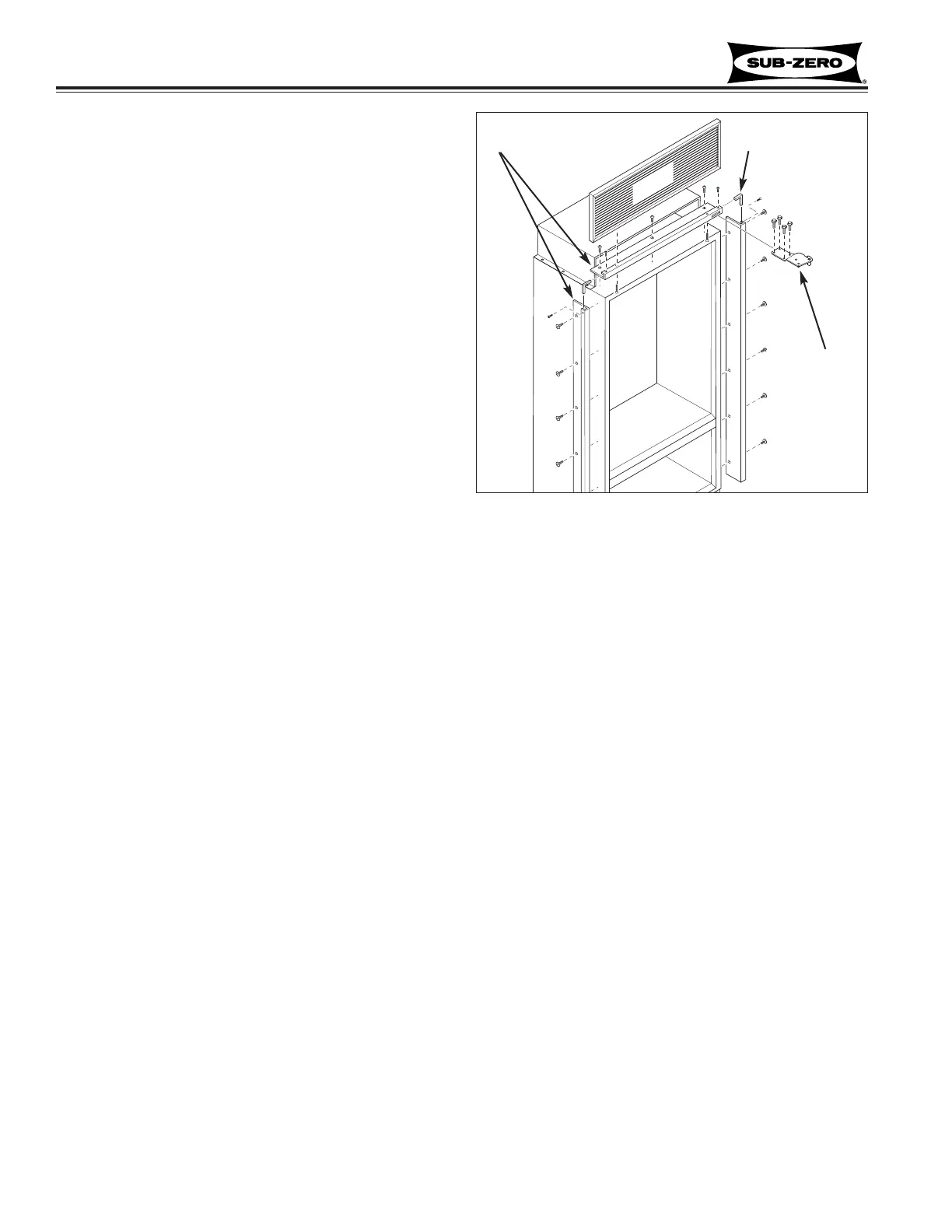
Mainframe Extrusion (All Models)
Mainframe extrusion is held to the sides of a unit with
low-profile 6-lobe drive screws, and at the top with
Phillips-head screws. Mainframe angles at the top cor-
ners strengthen and support mainframes at a 90° angle.
Side Mainframe Extrusion, (See Figure 7-31):
1. Pull unit from its installation approximately 4”.
2. Remove grille.
3. Remove aluminum tape from top corner.
4. Remove nut from bottom hinge stud (if applicable).
5. With a T-20 6-lobe bit, extract mounting screws.
6. With a small Phillips-head bit, extract screw at top
of mainframe angle and pull extrusion from unit.
Top Mainframe Extrusion, (See Figure 7-31):
1. Pull unit from its installation approximately 4”.
2. Remove grille.
3. Remove aluminum tape from corners.
4. Remove door(s) and top cabinet hinge(s).
5. With a Phillips-head bit, extract mounting screws.
6. With small Phillips-head bit, extract screws at side
of mainframe angles and pull extrusion from unit.
Figure 7-31. Mainframe Extrusion
Grille
Cabinet
Hinge
Mainframe Angle
Mainframe