7-54
Component Access / Removal
Built-In
Built-In
(600-
(600-
2
2
)
)
Series
Series
#3758407 - Revision B - August, 2006
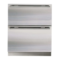
Evaporator Defrost Heater (685-2, 695-2)
The defrost heater sits under the evaporator, fitting into
a slot at bottom of the evaporator back bracket, with a
heater clip holding the other end of the heater.
To remove the defrost heater, the juice can rack, evapo-
rator front cover/light assembly, lower evaporator
cover/light assembly, freezer fan cover, and evaporator
cover assembly will need to be removed first, then (See
Figure 7-142):
1. Disconnect heater wire leads from wire harness.
2. Pull defrost heater toward front of unit.
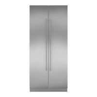
Freezer Evaporator Fan Assembly (685-2, 695-2)
Holes in the back flange of the freezer evaporator fan
assembly fit over pegs in the back wall. A screw
through the front flange holds the assembly to the left
wall.
To remove the evaporator fan assembly, the juice can
rack, evaporator front cover/light assembly, lower evap-
orator cover/light assembly, freezer fan cover, and
evaporator cover assembly will need to be removed
first, then (See Figure 7-143):
1. Extract the screws from the back and left side walls.
2. Pull assembly forward.
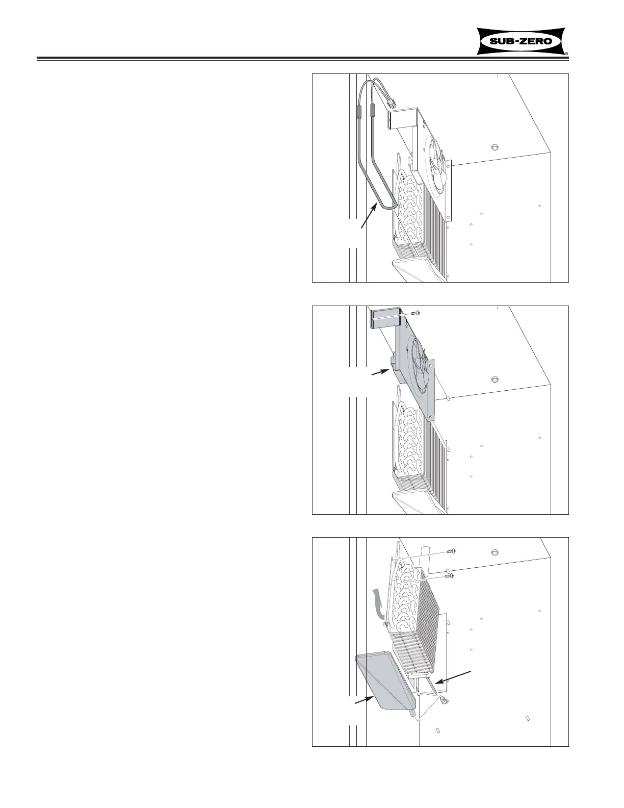
Freezer Drain Pan and Drain Tube Heat Conductor
(685-2, 695-2)
The drain tube heat conductor is riveted to the bottom
of the evaporator back bracket, and protrudes into the
drain pan spout. The support, attached to the evapora-
tor cover assembly, holds the drain pan front in place.
To remove the drain pan, the juice can rack, evaporator
front cover/light assembly, lower evaporator cover/light
assembly, freezer fan cover, evaporator cover assembly
and evaporator fan assembly will need to be removed
first, then (See Figure 7-144):
1. Extract screws securing evaporator to wall.
2. Pull evaporator assembly forward and up, until
drain tube heat conductor clears drain pan spout.
3. Pull drain pan forward.
Figure 7-142. Defrost Heater
Figure 7-144. Terminator & Fan Delay Bimetal
Figure 7-143. Evaporator Fan Assembly
Defrost
Heater
Evaporator
Fan Assy
Drain
Pan
Heat Conductor
 Loading...