7-57
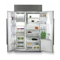
Built-In
Built-In
(600-
(600-
2
2
)
)
Series
Series
Component Access / Removal
#3758407 - Revision B - August, 2006
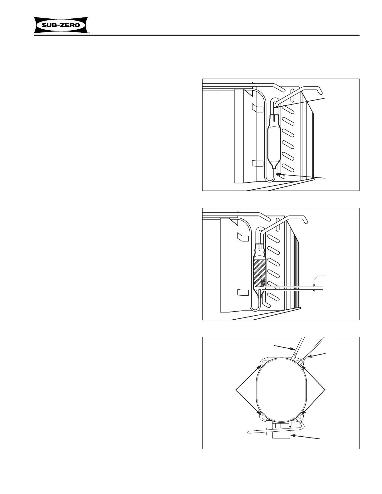
Filter-Drier (601R-2, 601RG-2, 601F-2)
The filter-drier is attached to the condenser outlet and
secured to the condenser with a cable tie.
After capturing the refrigerant from sealed system, (See
Figure 7-149):
1. Cut cable tie.
2. With a file, score a line around capillary tube 1” or
less from drier outlet, then fatigue capillary tube at
this line until it separates.
3. With a tube-cutter, cut inlet tube 1” or less from
drier inlet.
NOTE: It is not recommended to sweat tubing apart.
Doing so will induce moisture into the sealed system.
NOTE: After capillary tube separates, check tubing for
internal burrs. If burrs exist, repeat step 2 above.
NOTE: When installing replacement filter-drier, insert
capillary tube until it touches screen inside drier, then
pull capillary tube away from screen approximately 3/8"
(9.5 mm) before brazing (See Figure 7-150).
NOTE: Filter-drier outlet must be facing downward in
order to function properly.
Compressor (601R-2, 601RG-2, 601F-2)
The Compressor is secured to the unit tray by bolts into
grommets.
NOTE: When replacing a compressor, the filter-drier
must also be replaced.
After capturing the refrigerant from sealed system, (See
Figure 7-151):
1. Remove compressor electrical cover and discon-
nect electricals from compressor.
2. Extract bolts from grommets at each corner of com-
pressor base.
3. Pull compressor forward and rotate to the right to
gain access to suction and discharge lines.
4. Using a tube cutter, cut suction and discharge lines
approximately 1” from compressor.
NOTE: It is not recommended to sweat tubing apart.
Doing so will induce moisture into the sealed system.
SEALED SYSTEM (MODELS 601R-2, 601RG-2, 601F-2)
Figure 7-149. Filter-Drier
Filter-Drier
Cut here
Cut here
Figure 7-150. Filter-Drier Cut-Away View
3/8”
(9.5 mm)
Figure 7-151. Compressor Top View
Compressor
(Actual porting
may vary)
Electricals
BoltsBolts
Cut here
Cut here
 Loading...