7-60
Component Access / Removal
Built-In
Built-In
(600-
(600-
2
2
)
)
Series
Series
#3758407 - Revision B - August, 2006
Heat Exchanger (601R-2, 601RG-2, 601F-2)
NOTE: When replacing a heat exchanger, the filter-
drier must also be replaced.
NOTE: It is not necessary to pull the unit from its
installation in order to replace a heat exchanger. The
heat exchanger travels through tubing channel which is
foamed into the rear wall of the unit.
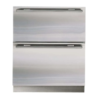
After capturing the refrigerant from the sealed system
(See Figures 7-155, 7-156 and 7-157):
1. Extract screws which hold evaporator to rear wall.
2. Pull bottom of evaporator up and rotate heat
exchanger out.
3. With a file, score a line around capillary tube, 1” or
less from evaporator inlet, then fatigue capillary
tube at this line until it separates.
4. With a tube-cutter, cut evaporator outlet 1” or less
from accumulator (if applicable), or 1” or less from
suction line connection point.
5. With a tin snips, or similar tool, cut heat exchanger
in compartment as close to tubing channel as pos-
sible.
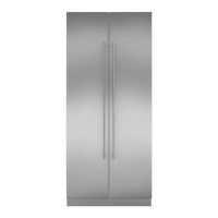
6. In lower compressor area, use a tube-cutter to cut
drier from condenser.
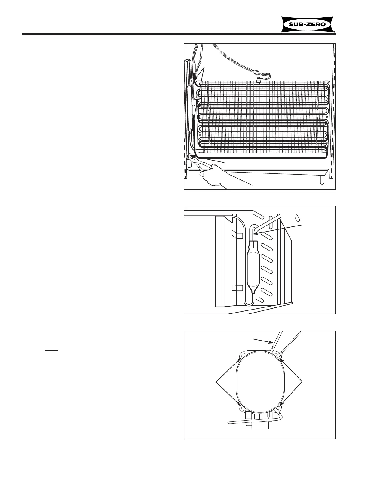
7. Extract bolts from grommets at each corner of com-
pressor base.
8. Pull compressor forward and rotate to gain access
to suction line.
9. Using a tube cutter, cut suction line approximately
1” from compressor.
10. Pull remaining heat exchanger from tubing channel.
NOTE: It is not recommended to sweat tubing apart.
Doing so will induce moisture into the sealed system.
NOTE: When replacing the heat exchanger, it is rec-
ommended to attach it at the evaporator end first, then
feed heat exchanger down through the tubing channel.
NOTE: After heat exchanger is installed, the tubing
channel must
be sealed closed with silicone.
Figure 7-155. Heat Exchanger
Cut Here
Cut Here
Figure 7-156. Filter-Drier
Filter-Drier
Cut here
Figure 7-157 Compressor Top View
Compressor
(Actual porting
may vary)
BoltsBolts
Cut here
 Loading...