Icemaker Information
600 Series
(Prior to #1810000)
6-6
#3756270 - Revision B - January, 2006
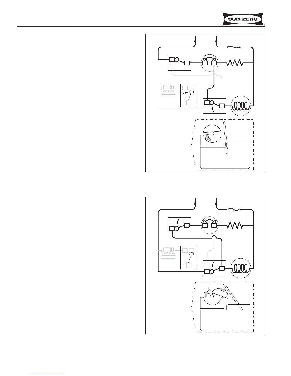
End of First Revolution (See Figure 6-7)
• The water valve solenoid switch is tripped by the
timing cam back to “normally open.”
• The timing cam trips the holding switch to “normally
close,” which ends the first revolution, but the ther-
mostat is still closed, so the motor is again started.
• The mold heater remains energized through the
thermostat.
Figure 6-7. End of First Revolution
Start of Second Revolution:(See Figure 6-8)
• The water valve solenoid switch is tripped by the
timing cam back to “normally open.”
• The timing cam trips the holding switch to “normally
close,” which ends the first revolution, but the ther-
mostat is still closed, so the motor is again started.
• The mold heater remains energized through the
thermostat.