Do you have a question about the Sub-Zero 600 Series and is the answer not in the manual?
Provides an overview of the manual's purpose and scope for the 600 Series units.
Lists contact information and resources for technical support and questions.
Details crucial safety warnings, symbols, and precautions for safe operation.
Summarizes the different warranty coverages provided for the units.
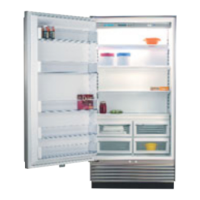
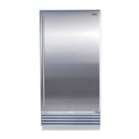
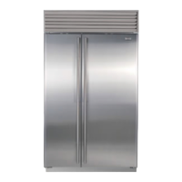
Outlines the various 600 Series models and their cosmetic variations.
Covers essential factors for proper unit installation to prevent service issues.
Explains the procedure for ensuring the unit is correctly leveled.
Details how to adjust doors for proper alignment and sealing.
Provides specific steps for aligning side-by-side refrigerator and freezer doors.
Guides on how to adjust freezer drawers for correct fit and operation.
Describes the process for installing or removing door panels.
Explains the installation of optional door stop cams for specific angles.
Defines key terms and components of the electronic control system.
Illustrates the fundamental architecture of the unit's electronic control.
Provides a diagram and table detailing control board connections and functions.
Explains how to perform basic functions like power, temperature, and icemaker control.
Covers special functions such as Show Room Mode and Sabbath Mode.
Details how the system monitors and regulates various unit operations.
Lists and explains common error codes displayed on the unit's LCD.
Outlines steps to enter and use the diagnostic mode for troubleshooting.
Provides essential guidelines and precautions for working with 134a refrigerant.
Lists important safety and procedural rules for handling refrigerant.
Details common sealed system problems and their corresponding repair steps.
Illustrates the flow of refrigerant through the system's main components.
Explains air circulation paths and specifies fan blade spacing for different models.
Provides an overview of the icemaker system and its components.
Describes the function and purpose of each part of the icemaker assembly.
Details the cycle of operation for the icemaker through electrical schematics.
Explains the various methods to manually halt ice production.
Provides instructions on how to manually initiate an icemaker cycle.
Guides on how to adjust the amount of water dispensed per cycle.
Details removal procedures for basic components like light diffusers and shelves.
Covers access and removal of major refrigerator section parts.
Details access and removal for freezer section components.
Explains how to access components in the lower compressor area.
Covers access and removal of components in the upper compressor area.
Details the procedure for accessing and removing the water valve.
Outlines procedures for accessing and removing sealed system parts.
Explains how to navigate and utilize the troubleshooting section effectively.
Provides codes to identify thermistor locations for diagnostic purposes.
Addresses issues with warm freezer temps and the VACUUM CONDENSER indicator.
Addresses issues with warm refrigerator temps and VACUUM CONDENSER indicator.
Troubleshooting steps for when the unit's lights are not functioning.
Covers common problems and solutions related to icemaker operation.
Lists normal operating pressures and pressure indications for sealed systems.
Details repair steps for common sealed system problems.
Provides procedures to test the integrity of the control panel's membrane switch.
Presents technical specifications and operating data for the 601R model.
Presents technical specifications and operating data for the 601F model.
Presents technical specifications and operating data for the 611 model.
Presents technical specifications and operating data for the 632 model.
Presents technical specifications and operating data for the 642 model.
Presents technical specifications and operating data for the 650 model.
Presents technical specifications and operating data for the 690 model.
Visual representation of electrical connections for the 601R model.
Simplified diagram showing the electrical flow and components for the 601R model.
Visual representation of electrical connections for the 601F model.
Simplified diagram showing the electrical flow and components for the 601F model.
Visual representation of electrical connections for the 611 and 650 models.
Simplified diagrams showing electrical flow for the 611 and 650 models.
Visual representation of electrical connections for the 632 and 642 models.
Simplified diagrams showing electrical flow for the 632 and 642 models.
Visual representation of electrical connections for the 690 model.
Simplified diagram showing the electrical flow and components for the 690 model.
| Type | Built-In |
|---|---|
| Energy Star Certified | Yes |
| Ice Maker | Yes |
| Lighting | LED |
| Door Alarm | Yes |
| Temperature Alarm | Yes |
| Configuration | Side-by-Side |
| Width | 36 inches |
| Height | 84 inches |
| Water Dispenser | Yes |
| Shelves | Adjustable glass shelves |


