Dimensions in parentheses are in
millimeters unless otherwise specified.
42
FRAMED CABINETRY –
BEADED INSET APPLICATION
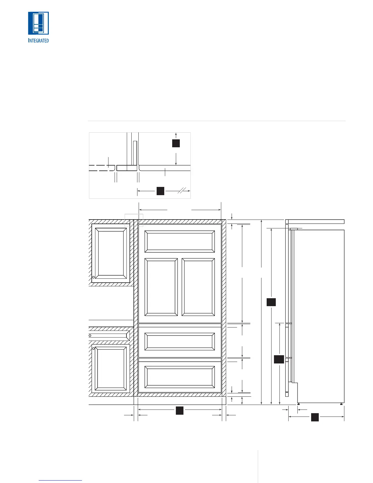
The illustration below shows a Model 736TC(I)
installed within a framed cabinetry beaded inset
application. Review, giving particular attention to
the overall panel specifications. Also refer to the
full-scale illustrations at the end of this section
for specifics on door openings.
MODEL 736TC(I)
Installation of the
Model 736TC(I)
Integrated tall unit
within framed
cabinetry.
*Dimensions may vary.
Dimensions are based
on a
1
/8" (3) reveal. A
reveal of up to
1
/4" (6)
is possible, but panel
dimensions need to be
adjusted accordingly.
INSTALLATION
To install integrated
panels, see the
detailed procedures
outlined in the
Sub-Zero Integrated
Installation Guide.
A) ALL REVEALS ARE 1/8" (3)
B) DRAWER RAILS ARE ATTACHED TO DRAWER FRONTS
C) BOTTOM RAIL MUST BE REMOVABLE
*DIMENSIONS MAY VARY
C
A
A
A
B
B
TOP VIEW
A A
DOOR PANEL
CABINET DOOR
TO WALL
SUB-ZERO
UNIT
PANEL WIDTH
1
1
/2"
(38)
1
1
/2"
(38)
47
7
/8"
(1216)
FRONT VIEW SIDE VIEW
35
3
/4" (908)
13
9
/16"
(345)
15
1
/16"
(383)
84"
(2624)
1
1
/2"
(38)
1
1
/2"
(38)
4"*
(102)
4" (102)
80"*
(2032)
24"
(610)
36"
(914)
SHADED AREA
INDICATES STATIONARY
STYLES AND RAILS
36"
(914)
24"
(610)
34
1
/
2
"
(876)
*