7-50
Component Access / Removal
Built-In
Built-In
(600-
(600-
2
2
)
)
Series
Series
#3758407 - Revision B - August, 2006
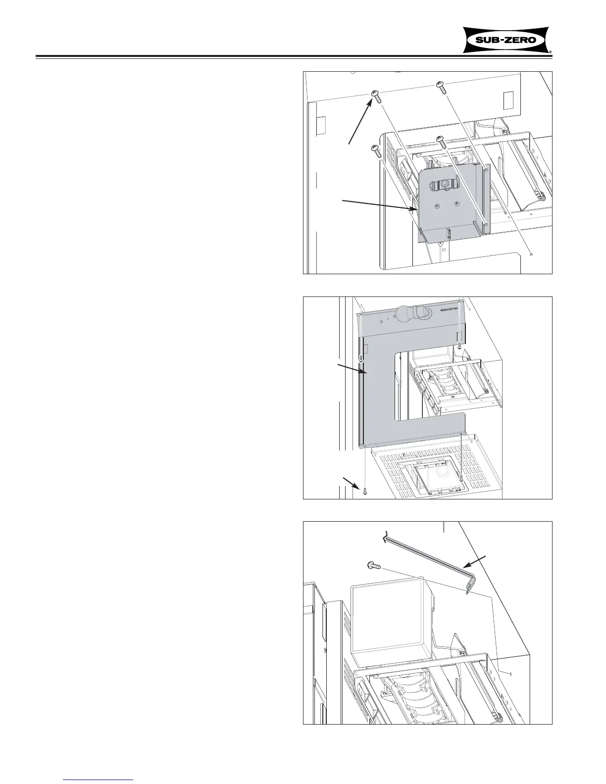
Ice Auger Motor Assembly (685-2, 695-2)
The ice auger motor assembly consists of the ice auger
motor and two icemaker switches. It is attached to the
rear wall with screws, directly behind the ice bucket
assembly.
To remove the ice auger motor assembly, the juice can
rack and ice bucket must first be removed, then (See
Figure 7-130):
1. Extract screws securing ice auger motor assembly
to rear wall.
2. Disconnect auger motor and icemaker switches
electrical leads, then pull assembly out.
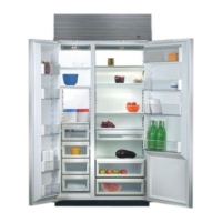
Freezer Evaporator Front Cover/Light Assy
(685-2, 695-2)
The freezer evaporator front cover/light assembly is
held in place by two screws at top, and two screws
through the bottom flange into the lower evaporator
cover/light assembly.
To remove the evaporator front/light assembly, the juice
can rack must first be removed, then (See Figure 7-
131):
1. Extract screws from bottom flange.
2. Extract screws from top flange.
3. Lower evaporator front cover down and disconnect
lighting electrical leads.
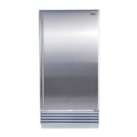
Freezer Compartment Thermistor (695-2 only)
NOTE: The model 685-2 freezer compartment thermis-
tor is located behind the evaporator front cover, just
inside the air duct. See “Freezer Compartment
Thermistor (685-2)” later in this section.
The 695-2 freezer compartment thermistor is located on
the mullion wall by the icemaker.
To remove the compartment thermistor, the juice can
rack, ice bucket and freezer evaporator front cover/light
assembly must be removed first, then (See Figure 7-
132):
1. Disconnect thermistor electrical leads.
NOTE: On newer models the thermistor is hard-
wired to the control board, so it will be necessary to
cut the thermistor wires to remove it.
2. Extract screw securing thermistor to wall.
Extract
Screws (4)
Figure 7-130. Ice Auger Motor
Auger
Motor
Assy
Figure 7-132. 695-2 Compartment Thermistor
Figure 7-131. Evaporator Front/Light Assembly
Extract
Screws (4)
Evap
Front/
Light
Assy
695-2
Freezer
compartment
thermistor