EasyManua.ls Logo

Sub-Zero BI Series - User Manual

Sub-Zero BI Series
15 pages
To Next Page IconTo Next Page
Loading...
Electronic Control System
3-31
#7005333 - Revision A - January, 2008
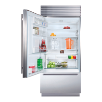
Built-In (BI) Series
Monitor Compressor Run Duration, Displays If Service is Needed
The microprocessor observes the changing state of the compressor relays on the control board to determine the
length of compressor run time (See Figure 3-50). Other than during initial pull down, if a compressor runs 100%
(Freezer = 6 hours / Refrigerator = 4 hours), five consecutive times, a fault code is logged, defrost is initiated, and
the service icon will flash. If approximately twenty-four (24) hours worth of 100% run periods occur, and the com-
partment temperature does not fall to at least the average of the set point and low off-set temperature (and the door
is not opened during the last run period), then the service icon will flash and the alarm will chime (See Figure 3-51).
NOTES:
If the unit is ever switched OFF then back ON, compressors will not energize for at least three (3) minutes. This
minimum OFF time is used to protect the compressor and its electricals.
To clear error indicators and Fault Codes the problem must be corrected, then press the ALARM key for fifteen
(15) seconds. Failure to clear Fault Codes will result in the highest priority error indicator reappearing in the LCD
when the unit is
switched back ON.
Figure 3-50. Signal Trace Schematic: Monitoring Compressor Run Times
P17
P1
P18
P9
P8
1
6
P16
P3
P5
1
P14
P15
LIGHTS
MAIN
L1L1
COMP2
HTR
DEFROST
COMP1
NEUTRAL
1146 5 83
P2
9
P7
P6
MAIN
CONTROL
BOARD
DRAWER LIGHTS
M
IM
CONDENSER FAN MOTOR
WHITE/RED
TAN
PINK
160 Ω
WHITE
WHITE
WHITE
WHITE
WHITE
TAN/WHITE
REFRIGERATOR LIGHTS
AIR FILTER LIGHT
FREEZER LIGHTS
FILL-TUBE HEATER2300-2900 Ω
ORANGE/BLACK
RED/WHITE
ORANGE
WHITE
WHITE
WHITE
WHITE
WHITE
WHITE
WHITE
STARTING RELAY
WHITE
WHITE
REFRIGERATOR
COMPRESSOR
STARTING RELAY
WHITE
FREEZER COMPRESSOR
PURPLE
GRAY
DEFROST
TERMINATOR
N.C.
GRAY/WHITE
WHITE/BLUE
BLUE
WHITE
PURPLE
GRAY
RED
YELLOW
WHITE/BLUE
N.C.
BLUE
ORANGE
YELLOW
YELLOW
ORANGE/BLACK
BROWN
YELLOW
REFRIGERATOR
LIGHT
TERMINATOR
FREEZER LIGHT
TERMINATOR
FZ DOOR SWITCH
REF DOOR SWITCH
WHITE/BLUE
WHITE/RED
PINK
WATER FILTER SW
N.O.
RED
RED/WHITE
TAN
TAN/WHITE
BLACK
60 CYCLES
115 VOLTS
L1
NEUTRAL
WATER VALVE
WHITE
HIGH VOLTAGE
DEF HEATER27.9-30.9 Ω
PURE AIR WARMER COLDER WARMER COLDER ALARM POWER MAX ICE ICE MAKER LIGHTS
Figure 3-51. the Service Icon Flashing & Alarm Chiming = Service Needed Immediately
Power to compressors
monitored; fault code
logged if 100% run
observed and service
icon appears; if sever-
al 100% runs occur,
service icon flashes
and alarm chimes
Question and Answer IconNeed help?

Do you have a question about the Sub-Zero BI Series and is the answer not in the manual?

Sub-Zero BI Series Specifications

General IconGeneral
BrandSub-Zero
ModelBI Series
CategoryRefrigerator
LanguageEnglish

Related product manuals