3-13
Electronic Control System
7011902 - Revision A - October, 2009
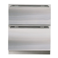
International Integrated
International Integrated
(ICB700 Base)
(ICB700 Base)
Series
Series
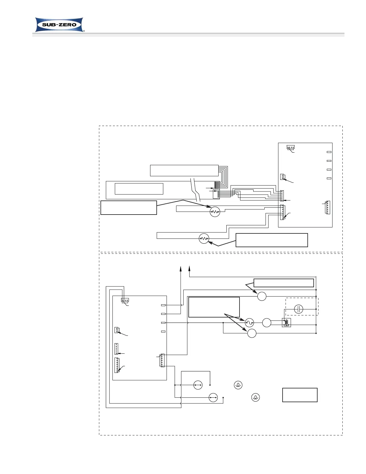
Regulate Refrigerator Zone Temperature (ICB700BR)
When the thermistor in the refrigerator compartment reaches high off-set temperature, calling for cooling, the evapo-
rator fan is energized, but the compressor and condenser fan are not allowed to run until the thermistor on the evap-
orator reaches 3°C (38°F). (See Figure 3-21)
If either drawer is opened while the evaporator fan is operating, the microprocessor will detect the power signal to
the lights and cut power to the fan.
Though compartment air temperatures will fluctuate, LCD displays average temperature.
NOTE: If compartment temperature exceeds either high or low offset (Ex: drawer is left open), temperature display
will change by one
degree per minute.
NOTE: If refrigerator
compartment thermis-
tor is faulty, compres-
sor operation defaults
to 20 minutes ON, 40
minutes OFF cycling,
EE appears in left of
LCD, SERVICE will
flash and Error Code
05 will be logged.
NOTE: If evaporator
thermistor is faulty,
the compressor will
not energize until
zone air temperature
exceeds high offset
by 3°C (38°F). SER-
VICE flashes and
Error Code 06 is
logged.
NOTE: When in
Sabbath Mode, the
refrigerator compart-
ment thermistor still
controls compressor
operation, except
there is a random 15
to 25 second delay
before the compres-
sor is energized.
Figure 3-21. ICB700BR Signal Trace - Regulate Refrigerator Zone
 Loading...