7-12
Component Access/Removal
7011902 - Revision A - October, 2009
International Integrated
International Integrated
(ICB700 Base)
(ICB700 Base)
Series
Series
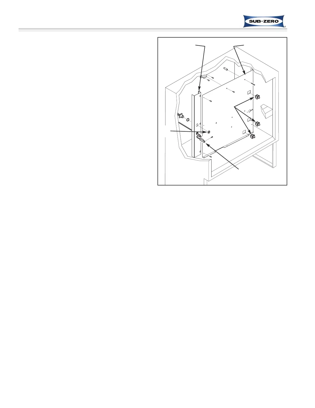
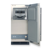
Figure 7-24. ICB700BFI Compartment Thermistor,
Air Ducts and Light & Fan Switches
Left Air Duct Main Air Duct
Thermistor
Nut
Switches
Freezer Light Switches and Icemaker Switch
Removal (ICB700BFI Only)
The light switches and fan switch are inserted into
square holes in the main air duct.
NOTE: The sump cover assembly must be removed
first.
To remove a switch (See Figure 7-24):
1. Extract the main air duct mounting screws and pull
duct to the left, then forward.
2. Disconnect switch electrical leads.
3. At back side of duct, depress tabs on each side of
switch while pushing switch out.
Freezer Compartment Thermistor Removal
(ICB700BFI Only)
The freezer compartment thermistor passes through a
hole in the left air duct from behind, and is attached to
the left wall of the compartment with a screw.
To remove the freezer compartment thermistor (See
Figure 7-24):
1. Extract thermistor mounting screw.
2. Remove nut from display wire harness Methode
connector.
3. Extract the left air duct mounting screws and pull
the duct forward.
4. Cut thermistor’s wire leads 152 mm (6'') to 305 mm
(12'') from the back wall, then pull thermistor from
compartment.