7-15
Component Access/Removal
7011902 - Revision A - October, 2009
International Integrated
International Integrated
(ICB700 Base)
(ICB700 Base)
Series
Series
COMPRESSOR AREA MECHANICAL
COMPONENTS
Main Control Board (ICB700BR Only)
The main control board is attached to the inside of the
control housing assembly with screws. The control
housing assembly is attached to the unit tray at the
front right corner.
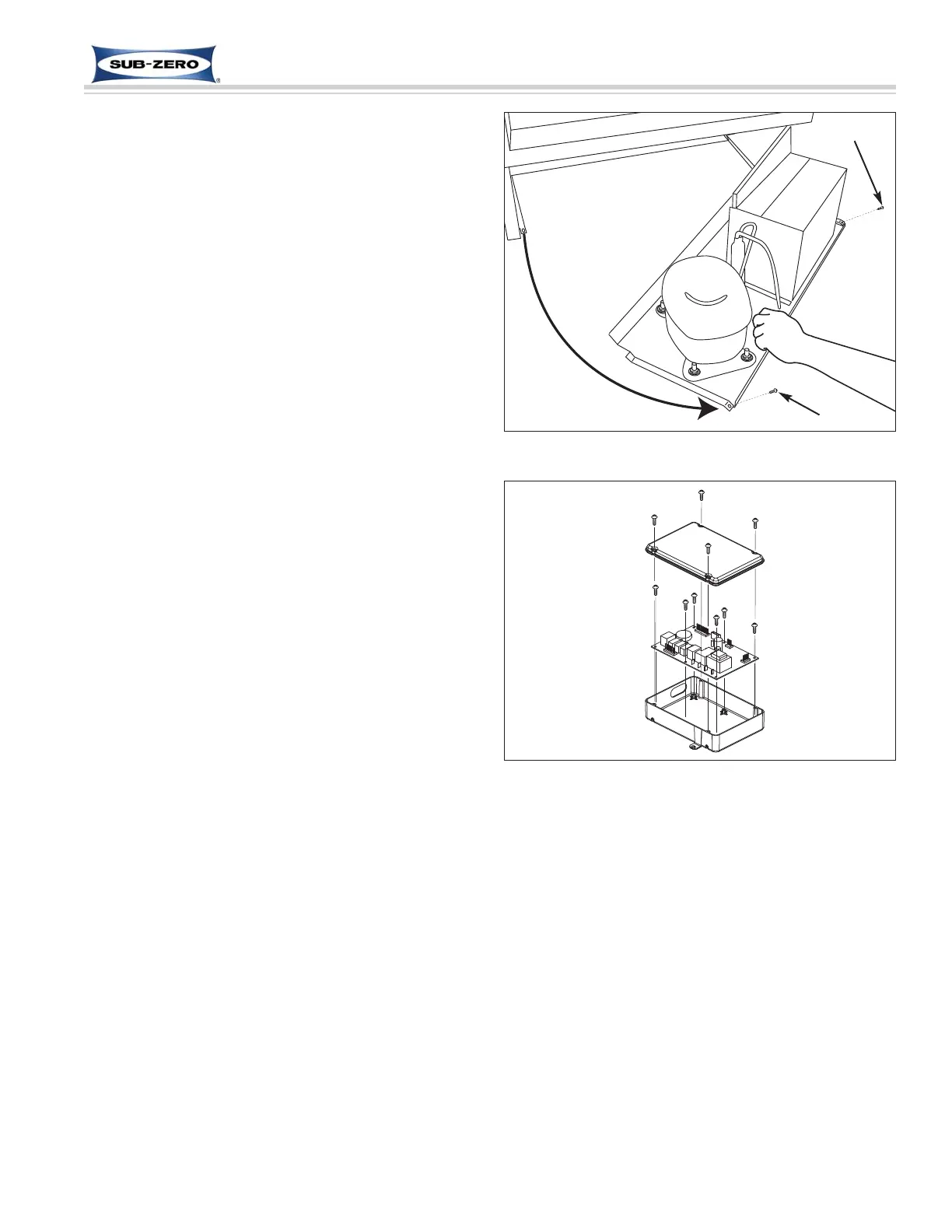
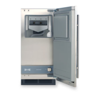
To remove the main control board, the kickplate/grill will
need to be removed first. Now, extract the two screws
that secure the unit tray to the unit and slide the tray
out (See Figure 7-31), then (See Figure 7-32).
1. Extract screws from control housing cover.
2. Disconnect all electrical lads from main control
board.
3. Extract screws which are holding control board in
control housing and lift control board out of housing.
Figure 7-32. ICB700BR Main Control Board
Figure 7-31. Sliding Unit Tray Out
Screw
Screw
Control Housing
Cover
Control Housing
Main Control
Board