7-21
Component Access/Removal
7011902 - Revision A - October, 2009
International Integrated
International Integrated
(ICB700 Base)
(ICB700 Base)
Series
Series
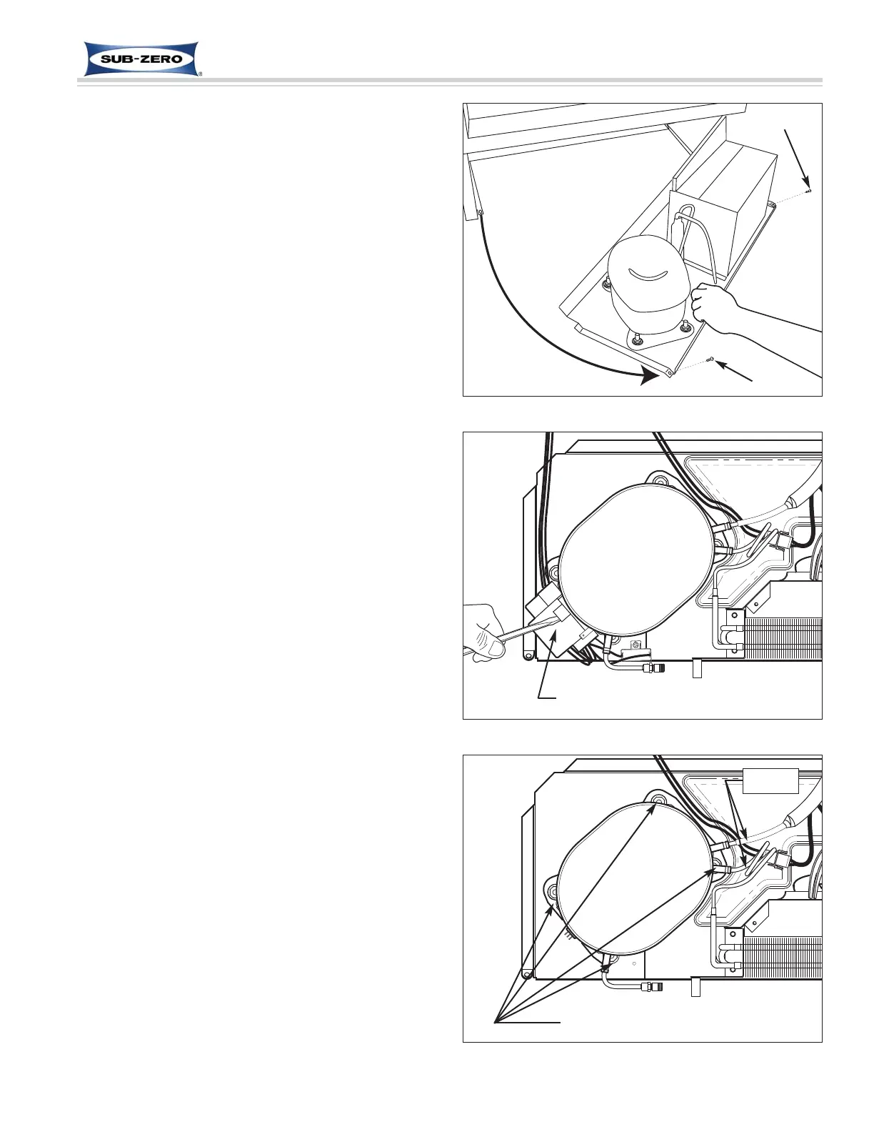
Figure 7-46. Sliding Unit Tray Out
Screw
Screw
Compressor Removal (All Base Units)
The compressor has four rubber compressor grommets
inserted into its base. Cylindrical metal spacers are
placed over threaded studs that are press fit to the unit
tray. The compressor grommets fit over the spacers
and a washer sets on top of the grommet and spacer.
A nut is then installed on the threaded stud and tight-
ened down on the washer and spacer.
NOTE: Before attempting to remove a compressor,
evacuate the refrigerant from the sealed system.
To remove the compressor, the kickplate/grill will need
to be removed first. Then, extract the two screws that
secure the unit tray to the unit and slide the tray out
(See Figure 7-46), then (See Figures 7-48 and 7-48).
1. Use a flat-blade screwdriver to remove compressor
electrical cover
2. Disconnect electrical leads from compressor.
3. Cut compressor inlet and outlet tubing with a tube
cutter, approximately 25 mm (1'') from compressor
ports.
4. Extract nuts and washers from threaded studs.
5. Lift compressor off of threaded studs.
NOTE: Sweating the joints apart is not recommended
as this may induce moisture into the sealed system.
NOTE: The high-side filter-drier must be replaced
whenever servicing the sealed system.
NOTE: When installing a compressor, be sure to thor-
oughly clean the tubing before brazing.
Figure 7-47. Removing Compressor Electrical Cap
Figure 7-48. Compressor Removal
Pry up with screwdriver
Cut here
Compressor
Compressor
Remove nuts and washers
 Loading...