7
Figure 9 - Locations of Screws in Back
of Furnace Cabinet (25,000 BTU/Hr
Model)
Figure 10 - Locations of Screws in
Back of Furnace Cabinet (40,000
BTU/Hr Model)
Figure 11 - Removing Screws on Lower
Flange (40,000 BTU/Hr Model Shown)
Figure 13 - Location of Knockout Plug
Figure 14 - Inserting Pipe through
Knockout Hole
Figure 12 - Disconnecting Gas Inlet Pipe
(40,000 BTU/Hr Model Shown)
Figure 8 - Connecting Gas from Inside of
Room
INSTALLATION
(Continued)
Connecting Furnace to Gas
Supply at Front of Furnace
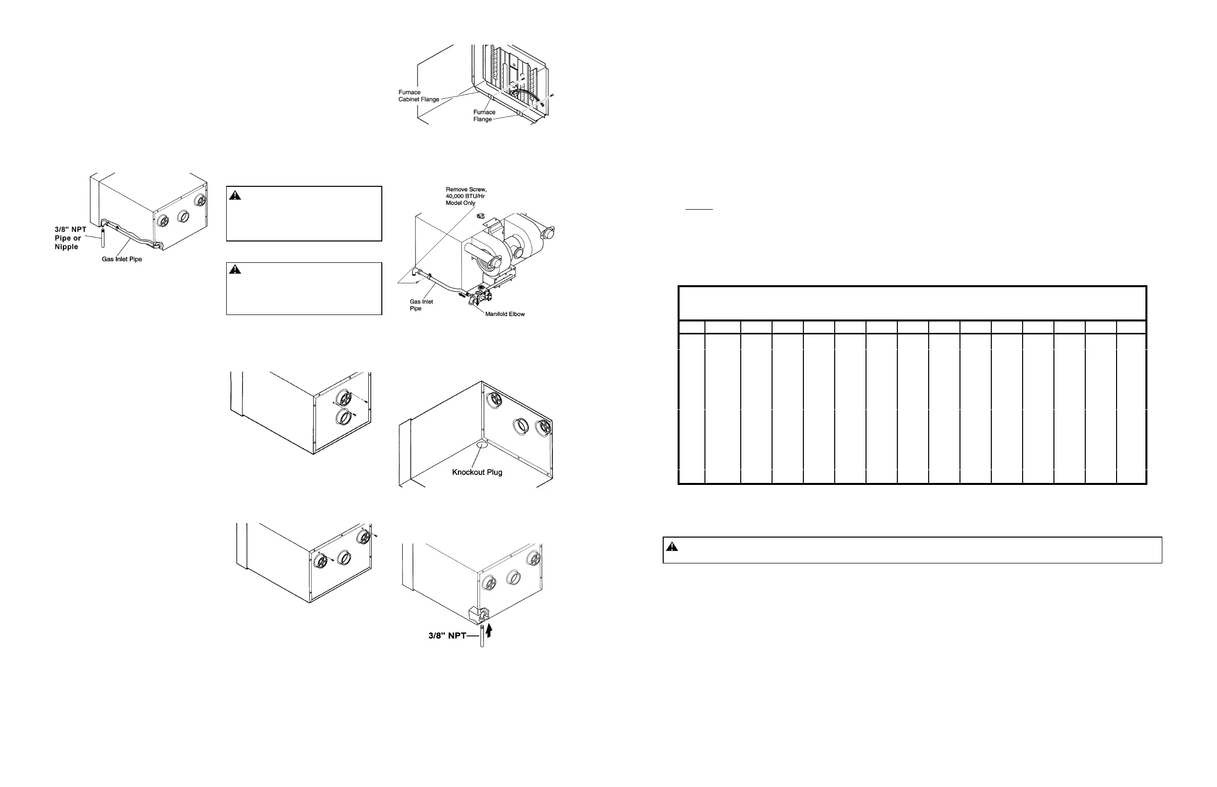
1. Locate gas inlet pipe on lower, right
front of furnace (see Figure 8).
2. Connect 3/8" NPT pipe or nipple to
gas inlet pipe (see Figure 8). See
Providing Gas Piping to Furnace for
correct gas pipe installation.
Connecting Furnace to Gas
Supply at Rear of Furnace
1. Remove the two screws in back of fur-
nace cabinet located by the exhaust
vent(s) (see Figures 9 and 10).
2. Remove two screws on front lower
flange that attach furnace flange to
furnace cabinet flange (see Figure
11). Note: 40,000 BTU/Hr model has
a bottom shield (see parts list, page
19, for location). Removing two
screws will detach bottom shield.
3. Slide furnace out of furnace cabinet.
4. Locate gas inlet pipe on lower, right
front of furnace.
5. 40,000 BTU/Hr Model Only: Remove
screw holding gas inlet pipe clamp to
furnace. (See Figure 12).
6. Disconnect gas inlet pipe from 3/8"
manifold elbow. Turn gas inlet pipe
counterclockwise to disconnect (see
Figure 12).
7. Rotate the 3/8" manifold elbow 90/ so
the opening is pointing downward
(see Figure 12).
8. Locate knockout plug in furnace cabi-
net. Knockout plug is in lower left rear
of furnace cabinet (as viewed from
rear, see Figure 13). Remove
knockout plug.
9. Slide furnace back into furnace cabi-
net. Make sure exhaust tube gaskets
are in place. Make sure exhaust and
intake vent tubes extend into vent
caps on back of cabinet. Replace two
screws by exhaust vent(s) removed in
step 1.
10. 25,000 BTU/Hr Model: Replace two
screws removed in step 2. Attach fur-
nace flange and furnace cabinet
lower flange together.
40,000 BTU/Hr Model: Place bottom
shield back in place. Replace two
screws removed in step 2. Attach bot-
tom shield, furnace flange, and
furnace cabinet lower flange together.
11. Run 3/8" pipe or nipple through
knockout hole. Connect 3/8" pipe or
nipple to manifold elbow (see Figure
14). See Providing Gas Piping to
Furnace for correct gas pipe instal-
lation.
CAUTION: Lightly apply pipe joint
sealant to male threads before
connecting. Use pipe joint sealant
that is resistant to liquid petroleum
(LP) gas.
12. Check connections for gas leak.
WARNING: Never use an open
flame to check for a leak. Apply a
mixture of liquid soap and water to
all joints. Bubbles forming show a
leak. Correct all leaks at once.
13. Caulk around pipe or nipple. This pre-
vents cold air entering knockout hole.
8
INSTALLATION
(Continued)
Providing Gas Piping to Furnace - Propane (LP) Gas Only
See Next Page for Natural Gas Piping
You must provide gas piping from gas source to furnace. The gas piping must be in a vertical position where it connects to the furnace.
This prevents interference with front cover installation.
Consult your local gas company for proper routing of the gas lines.
Pipe size is determined by the length of pipe from the gas source to the furnace and the total BTU load on the gas source.
Add the total BTUs required for all appliances connected to the gas source including this furnace. Divide this number by 2500. This
will give you the approximate cubic feet per hour needed.
Example:
40,000 BTU/Hr
+ 15,000 BTU/Hr for other gas appliances
55,000 BTU/Hr total
55,000 ÷ 2500 = 22
Locate 22 or higher on chart below.
According to the chart below, you should use 40 feet or less of 3/8" pipe, 125 feet
or less of 1/2" pipe, etc....
MINIMUM
RON PIPE
SIZE LENGTH OF PIPE (FEET)
10 20 30 40 50 60 70 80 90 100 125 150 175 200
3/8"
47 32 26 22 19 18 16 15 14 13 12 11 10 —
1/2"
87 61 48 42 37 33 30 28 26 25 22 20 18 17
3/4"
184 126 100 86 76 69 63 59 55 52 48 42 39 36
1"
344 232 189 162 142 129 119 112 106 99 86 79 73 66
1¼"
696 484 391 331 291 265 245 232 212 202 182 166 149 139
1½"
1060 729 590 504 444 404 371 351 324 305 272 252 232 212
2"
2022 1392 1094 961 842 762 696 656 616 576 517 470 430 404
2½"
3182 2188 1790 1524 1326 1226 1127 1060 994 928 829 749 969 649
3"
5635 3911 3116 2718 2387 2154 1989 1856 1724 1657 1458 1326 1226 1127
4"
11602 7956 6431 5503 4906 4508 4110 3845 3580 3381 2983 2718 2519 2320
IMPORTANT: Check gas line pressure at gas meter before connecting furnace to gas line. Gas line pressure must be no less than
11 inches of water and no greater than 13 inches of water. Gas pressures and input to the burners must not exceed the rated input
and pressure shown on the rating plate. For propane/LP gas, manifold pressure should be 10 inches of water. For elevations above
2000 feet, reduce rating 4% for each 1000 feet above sea level (U.S.A. only).
CAUTION: Never connect heater directly to the propane/LP supply. This heater requires an external regulator (not
supplied). Install the external regulator between the heater and propane/LP supply.
The installer must supply an external regulator. The external regulator will reduce incoming gas pressure. You must reduce incoming
gas pressure to between 11 and 14 inches of water. If you do not reduce incoming gas pressure, heater regulator damage could
occur. Install external regulator with the vent pointing down. Pointing the vent down protects it from freezing rain or sleet.
 Loading...