9
INSTALLATION
(Continued)
Providing Gas Piping to Furnace - Natural Gas Only
See Previous Page for LP Gas Piping
You must provide gas piping from gas source to furnace. The gas piping must be in a vertical position where it connects to the furnace.
This prevents interference with front cover installation.
Consult your local gas company for proper routing of the gas lines.
Pipe size is determined by the length of pipe from the gas source to the furnace and the total BTU load on the gas source.
Add the total BTUs required for all appliances connected to the gas source including this furnace. Divide this number by 1030. This
will give you the approximate cubic feet per hour needed.
Example:
40,000 BTU/Hr
+ 15,000 BTU/Hr for other gas appliances
55,000 BTU/Hr total
55,000 ÷ 1030 = 53.4
Locate 53.4 or higher on chart below.
According to the chart below, you should use 50 feet or less of 1/2" pipe, 200 feet
or less of 3/4" pipe, etc....
MINIMUM
RON PIPE
SIZE LENGTH OF PIPE (FEET)
10 20 30 40 50 60 70 80 90 100 125 150 175 200
3/8"
72 49 40 34 30 27 25 23 22 21 18 17 15 14
1/2"
132 92 73 63 56 50 46 43 40 38 34 31 28 26
3/4"
278 190 152 130 115 105 96 90 84 79 72 64 59 55
1"
520 350 285 245 215 195 180 170 160 150 130 120 110 100
1¼"
1050 730 590 500 440 400 370 350 320 305 275 250 225 210
1½"
1600 1100 890 760 670 610 560 530 490 460 410 380 350 320
2"
3050 2100 1650 1450 1270 1150 1050 990 930 870 780 710 650 610
2½"
4800 3300 2700 2300 2000 1850 1700 1600 1500 1400 1250 1130 1050 980
3"
8500 5900 4700 4100 3600 3250 3000 2800 2600 2500 2200 2000 1850 1700
4"
17500 12000 9700 8300 7400 6800 6200 5800 5400 5100 4500 4100 3800 3500
IMPORTANT: Check gas line pressure at gas meter before connecting furnace to gas line. Gas line pressure must be no less than
5 inches of water and no greater than 7 inches of water. Gas pressures and input to the burners must not exceed the rated input and
pressure shown on the rating plate. For natural gas, manifold pressure should be 3.5 inches of water. For elevations above 2000 feet,
reduce rating 4% for each 1000 feet above sea level (U.S.A. only).
10
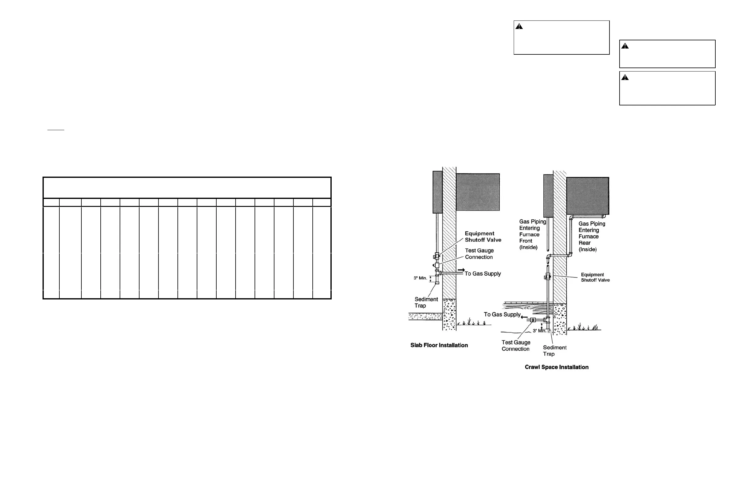
Figure 15 - Gas Connection
INSTALLATION
(Continued)
Installation must include an equipment
shutoff valve (supplied), ground joint
union, plugged 1/8" NPT tap, and a
sediment trap. Locate NPT tap within
reach for test gauge hook up. NPT tap
must be upstream from furnace (see
Figure 15).
Install an equipment shutoff valve in an
accessible location. The equipment
shutoff valve is for turning on or shutting
off the gas to the appliance.
Apply pipe joint sealant lightly to male
threads. Prevent excess sealant from
going into pipe. Excess sealant in pipe
could result in clogged furnace valves.
CAUTION: Lightly apply pipe joint
sealant to male threads before
connecting. Use pipe joint sealant
that is resistant to liquid petroleum
(LP) gas.
Install sediment trap in supply line as
shown in Figure 15. Locate sediment trap
where it is within reach for cleaning. A
sediment trap traps moisture and
contaminants. This keeps them from
going into furnace controls. If sediment
trap is not installed or is installed wrong,
furnace may not run properly.
IMPORTANT: Locate sediment trap
where trapped matter will not freeze.
Install sediment trap in a vertical run of
pipe. If gas piping enters furnace from
rear (outside), you must locate sediment
trap in crawl space (see Figure 15). If you
install furnace in structure with slab
foundation, you must install gas piping to
front of furnace (inside) (see Figure 15).
CHECKING GAS
CONNECTIONS
WARNING: Test all gas piping
and connections for leaks after
installation or servicing. Correct all
leaks at once.
WARNING: Never use an open
flame to check for a leak. Apply a
mixture of liquid soap and water to
all joints. Bubbles forming show a
leak. Correct all leaks at once.
Pressure Testing Gas Supply
Piping System
Test Pressures in Excess of 1/2 PSIG
(3.5 kPa)
1. Disconnect appliance with its
appliance main gas valve (control
valve) and equipment shutoff valve
from gas supply piping system.
Pressures in excess of 1/2 psig (3.5
kPa) will damage heater regulator.
2. Cap off open end of gas pipe where
equipment shutoff valve was
connected.
3. Pressurize supply piping system by
either using compressed air or
opening main gas valve located on or
near gas meter.
4. Check all joints of gas supply piping
system. Apply mixture of liquid soap
and water to gas joints. Bubbles
forming show a leak.
5. Correct all leaks at once.
6. Reconnect furnace and equipment
shutoff valve to gas supply. Check
reconnected fittings for leaks.
Test Pressures Equal To or Less Than
1/2 PSIG (3.5 kPa)
1. Close equipment shutoff valve (see
Figure 16).
2. Pressurize supply piping system by
either using compressed air or
opening main gas valve located on or
near gas meter.
3. Check all joints from gas meter to
equipment shutoff valve. Apply mix-
ture of liquid soap and water to gas
joints. Bubbles forming show a leak.
4. Correct all leaks at once.
 Loading...