30
SEQUENCE OF OPERATION
For Furnaces Equipped With Time Delay
The thermostat controls the operating circuit to the furnace by reacting to room temperature to open
and close a set of contact points which allows current to flow to the ON and OFF switch then to the
relay.
The relay receives the power and allows power to pass through to the switch within the relay. This
is done by a heater coil within the relay which actuates a bi-metal disc closing the relay circuit.
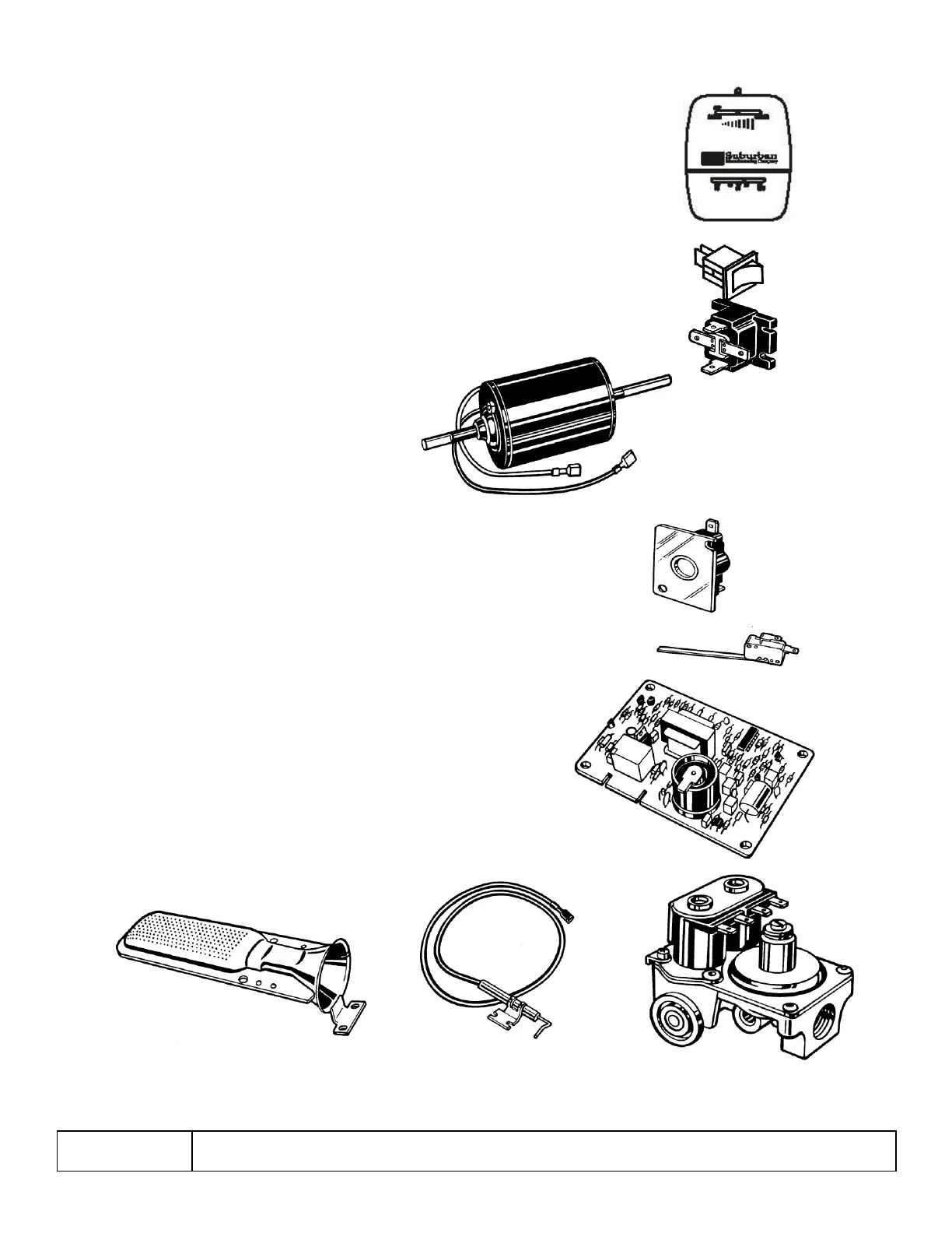
The power then flows to the motor and allows the blower to operate. One end of the motor shaft
drives the room air wheel. The other end of the motor shaft drives the combustion air wheel that
delivers the required air to the burner for combustion.
The limit switch is an in-line device which protects the furnace from over heating conditions. The
contacts in the limit switch open at a given temperature setting, shutting off power to the ignition
system which controls the gas valve.
As the room air wheel comes up to speed, air flow closes the
sail switch completing the circuit. The sail switch is placed
into the system as a safety to prove there is adequate air for combustion.
The next operation is controlled by the Direct Spark Ignition, (DSI) system
as power is applied to the DSI board. The system will do the following.
1. The board has a timing circuit which allows the blower
topurge the chamber of any products of combustion or gas.
2. The board will then apply power to the gas valve.
At thesame time it produces a high voltage power supply to the electrode producing spark at
the burner.
3. The board will also confirm the presence of a flame. Ifthe flame is not sensed after
7 seconds, the module will try two (2) more times and then go into lock-out. The flame is
sensed through the spark wire and electrode.
When the thermostat has reached the set point with the room air temperature,
the contacts will open removing power from the controls. The blower will remain
on until the relay opens and stops the motor.
NOTE: On some models, sail switch is before limit switch.
Sequence of Operation for Fan Control Module Board
Part Number 520820
 Loading...