The appliance must be isolated from the gas supply piping during any pressure
testing of the gas supply piping system at test pressure equal to or less than
1/2 PSIG.
1. A 3/8” male are connection is provided for gas line hookup. Some standards
may require the use of a manual shut off valve in the gas line external to the
furnace cabinet.
2. In order to maintain a check of gas supplied pressure to the furnace, Suburban advises
the installer to provide the 1/8” NPT plug tap for test gauge connection immediately
upstream of the gas supply connection to the furnace and that it be readily accessible.
3. After the furnace has been connected to the gas supply, all joints must be
checked for leaks.
WARNING! Never check for leaks with an open ame. Turn on the gas
and apply soapy water to all joints to see if bubbles are formed.
CONNECTING ELECTRICAL SUPPLY
CAUTION: This furnace is designed for negative ground 12 volt D.C.
system only. Do not attempt to alter the furnace for a positive ground
system or connect the furnace directly to 115 volts A.C. Damage to furnace
component parts will occur. Connect only to a protected circuit fused for
not more than 20 amps.
Be sure all wiring to the furnace is of heavy enough gauge to keep the voltage
drop through it to a minimum and to provide enough power for start-up surge.
No. 12 gauge wire is recommended. If any of the original wire that is supplied
with the appliance must be replaced, it must be replaced with type 105° C or its
equivalent.
Power supply connections are to be on the right side of the furnace. The wires
are color coded, red for positive (+) and yellow for negative (-). This polarity
must be observed so the furnace motor will run the proper direction of rotation to
insure correct air delivery. (See wiring diagram.)
If the furnace power supply is to be from a converter, we recommend that the
converter system used to power the furnace be wired in parallel with the battery.
This will serve two purposes:
1. Provide a constant voltage supply to the furnace.
2. Filter any A.C. spikes or volt surges.
CONNECTING DUCTS TO FURNACE
The following duct requirements must be followed in order to assure proper
operation of the furnace:
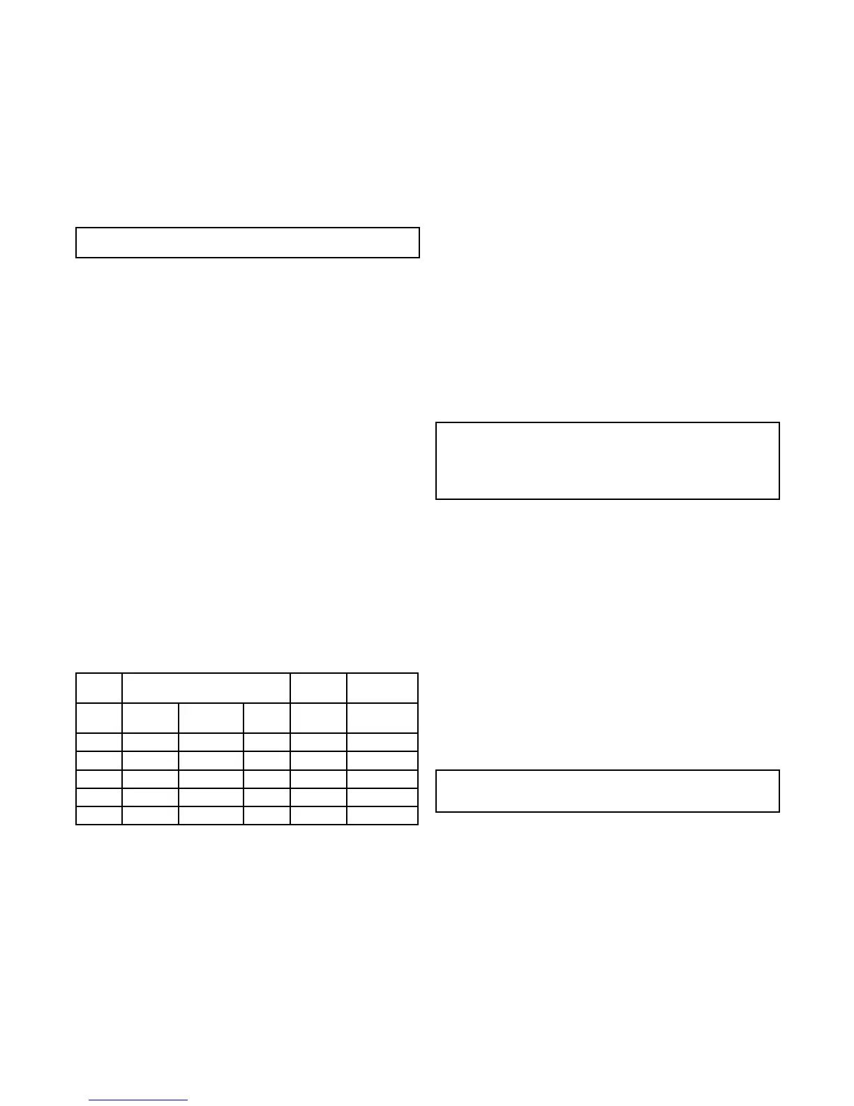
A. The minimum open duct areas listed below must be maintained throughout
entire duct system including through register:
MODEL SIDE DUCTS TOP
DUCT
BOTTOM
DUCT
Min. Open
Duct Area
Min No.
Ducts Used
Duct
Size
Min. Open
Duct Area
Min. Open
Duct Area
SF-20 25 SQ. IN. 2 4” 56 SQ. IN. 56 SQ. IN.
SF-25 36 SQ. IN. 3 4” 56 SQ. IN. 56 SQ. IN.
SF-30 36 SQ. IN. 3 4” 56 SQ. IN. 56 SQ. IN.
SF-35 48 SQ. IN. 4 4” 56 SQ. IN. 56 SQ. IN.
SF-42 48 SQ. IN. 4 4” 56 SQ. IN. *72 SQ. IN.
*SF-42 Bottom Duct requires use of Bottom Duct Kit, Part No. 520753
NOTE: Ducts terminating in a dead air space (like holding tank
compartments or cargo areas (Toy Boxes) with no means for return air
recirculation should not be counted in the required duct area. Also ducts
2” in diameter or smaller should not be counted in the required duct area.
B. No outlet register is to be placed within 18” of the return air opening. Any
register installed at 18” should never be toward the return air opening. If a register
is installed on a wall 90 degrees to the return air, it can be less than 18”.
C. Make the duct connections at the furnace cabinet tight. Loose connections
will result in overheating of the component parts on the furnace and a reduction
of the heated air ow through the duct system.
D. Avoid making any sharp turns in the duct system. Sharp turns will increase
the static pressure in the plenum area and could cause the furnace to cycle.
E. Avoid making a lot of turns in the duct system. The straighter the duct system,
the better the performance of the furnace.
F. Maintain a minimum of 1/4” clearance where ducts pass through any
combustible construction, such as coach cabinetry. (See Figure 3.) NOTE: UL
listed duct materials can be 0” clearance.
G. Do not install air boosters in the duct system. Such devices will cause the
furnace to cycle on limit and to have erratic sail switch operation.
NOTE: After installation of the furnace and duct system is completed, adjustments
must be made to obtain a temperature rise within the range specied on the
Rating Plate.
INSTALLING THERMOSTAT
The thermostat used with this unit must have NO voltage output to return leg
when there is not a call for heat or in the “OFF” setting.
Locate the room thermostat approximately 4-1/2 feet above the oor on an
inside bulkhead where it is not affected by heat from any source except room air.
Connect thermostat wiring to the blue wires on right side of furnace. (See wiring
diagram.) If your furnace is equipped with a thermostat that has an adjustable
anticipator, the anticipator should be set at .7 amps. If you desire longer heating
cycles, adjust the anticipator to a higher setting. If you desire shorter heating
cycles, adjust the anticipator to a lower setting. Adjustments to the anticipator
setting should be made in .5 amp increments.
PREVENTIVE MAINTENANCE
WARNING! If the user of this appliance fails to maintain it in the
condition in which it was shipped from the factory or if the appliance is
not used solely for its intended purpose or if appliance is not maintained
in accordance with the instructions in this manual, then the risk of a
re and/or the production of carbon monoxide exists which can cause
personal injury, property damage or loss of life.
CAUTION: Label all wires before disconnecting for servicing. Proper
polarity must be observed so the furnace motor will run with the proper
direction of rotation to insure correct air delivery. (See wiring diagram).
CAUTION: Label all wires prior to disconnection when servicing controls.
Wiring error can cause improper and dangerous furnace operation.
Always verify proper operation of furnace after servicing.
Your furnace should be inspected by a qualied service agency yearly before
turning the furnace on. Particular attention should be given to the following
items.
1. Inspect furnace installation and vent termination to be sure furnace is
properly secured in place (see Installation Instructions), that vent terminates
to the atmosphere, and that vent tubes overlap properly (see Installing Vent
Assembly.)
2. Inspect chamber and venting to assure that these components are physically
sound without holes or excessive corrosion and that the installation and/or re-
installation is in accordance with Suburban’s installation instructions. (Reference
installation manual supplied with furnace.)
WARNING! It is imperative that the products of combustion be properly
vented to atmosphere and that all combustion air supplied to burner be
drawn from outside atmosphere.
3. Check the base on which furnace is mounted. Be sure it is physically sound,
void of any sagging, deterioration, etc.
4. Inspect furnace, the venting, ducting and gas piping to furnace for obvious
signs of deterioration. Correct any defects at once.
5. Inspect combustion chamber for restrictions in exhaust or intake. It is
imperative that the ow of intake combustion air and the ow of exhaust gases
being expelled to the outside atmosphere not be obstructed. Any soot or loose
debris should be blown out using compressed air. (See Figure 7.)
6. Inspect all gaskets. If any gaskets show signs of leakage or deterioration,
replace them. Safe operation of the furnace depends on all gaskets being tight.
7. Inspect return air inlet openings to the furnace. Remove any restrictions to
assure adequate air ow.
You, as the owner/user, should inspect the furnace monthly during the
heating season for presence of soot on vent. Operating the furnace under this
condition could lead to serious property damage, personal injury or loss of life.
4
 Loading...