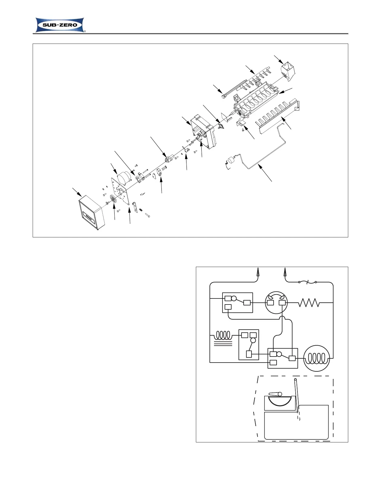
Figure 6-1. Diagram of Icemaker Components
(For reference only. Individual components are not available for Service. If problems with the icemaker are
discovered, the entire icemaker must be replaced)
ICEMAKER OPERATION
The following series of electrical schematics illustrate a
typical icemaker cycle of operation. Below each
schematic is a diagram indicating the approximate loca-
tion of the ice ejector and ice level arm during the
phase the schematic indicates.
Freeze Phase of Ice Making Cycle (See Figure 6-2)
• The ice mold is filled with water.
• The thermostat is open.
• No icemaker components are energized.
Figure 6-2. The Freeze Phase