SRC Service Manual
Revision 02
Aug 2007
4.3
Controls on the SRC-250 to 1000
The microprocessor controls on the Sullair SRC-250 to 1000 Cycling Dryers allows you to turn the
dryer on and off, controls the operation of the dryer, and continuously monitors the working
parameters, informing the user of possible problems through lights, alarms and a digital display.
In addition, the microprocessor also:
- Records and displays the last 8 warnings or alarms,
- Records the working hours of the dryer and refrigerant
compressor,
- Provides a Service Required warning at a pre-set interval,
- Controls the cycling operation of the refrigerant
compressor, and
- Controls operation of the condensate drain.
The microprocessor can also be connected to an external Modbus RTU protocol compatible system
by installing an (optional) RS-485 communication port. See Section 10.5 for further information.
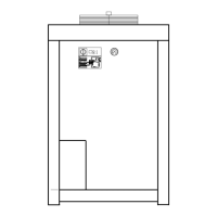
The electrical panel is located inside the dryer and positioned for easy access. It is directly accessible
from the front via a hinged door, with a door lock integrated into the dryer’s main switch.
The power section comprises a main isolator switch, protection against motor over current, and a
series of contactors.
4.3.1 Inputs
Consists of both analog inputs (J2) and digital inputs (J1 & J3).
Analog Inputs (J2)
J2 1 GND Ground for temperature sensors.
J2 2 B1 Dewpoint Temperature Sensor (B1)
J2 3 B2 Coolant Temperature Sensor (B2)
Digital Inputs (J1 & J3)
J1 2 0V Power (Ground)
J1 3 24V Power (24Vac)
J1 5 ID1 High Pressure Switch (HP Alarm)
J1 8 ID2 Low Pressure Switch (LP Alarm)
J1 11 ID3 Remote On-Off
J3 1 IDC2 Common (Ground)
J3 2 ID4 Drain Level Sensor
J3 3 +5V Power Input to Drain Level Sensor
Page 22 of 56
 Loading...