SRC-- 1 5 0 --- S RC -- 1000
2
English
3.3 Versions
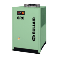
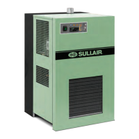
Air---cooled version (Ac)
Y Do not create cooling air recirculation situations. Do not
obstruct the ventilation grilles.
3.4 Tips
Y To prevent damage to the internal parts of the dryer and air
compressor, avoid installations where the surrounding air con-
tains solid and/or gaseous pollutants (e.g. sulphur, ammonia,
chlorine and installations in marine environments).
3.5 Electrical connection
Use approved cable in conformity with the local laws and regula-
tions (for minimum cable section see par. 8.3).
Connected to terminals “L and N ” for single---phase machines
a n d t o t e r m i n a l s “ L 1 --- L 2 --- L 3 ” f o r t h r e e --- ph a s e m a c h i n e s .
Install a differential thermal magnetic circuit breaker with con-
tact opening distance of 0.12 inches (3 mm) ahead of the system
(IDn = 0.3A) (see the relevant current local regulations).
3.6 Condensate drain connection
Y Make the connection to the draining system, avoiding con-
nection in a closed circuit shared by other pressurized discharge
lines. Check the correct flow of condensate discharges. Dispose
of all the condensate in conformity with current local environ-
mental regulations.
4 Commissioning
4.1 Preliminary checks
Before commissioning the dryer, make sure:
a) installation was carried out according to that given in the sec-
tion 3;
b) the air inlet valves are closed and that there is no air flow
through the dryer;
c) the power supply is correct;
4.2 Commissioning
Start the dryer before the air compressor;
For models SR C-- 150 --- SRC -- 200 (see par. 5.1):
S switch the power on by turning the Main disconnector switch
& to “I ON” so that the green line lamp illuminates.
For models SR C-- 250 --- SRC -- 1000 (see par. 5.2):
S switch the power on by turning the MAIN SWITCH
& to
“I ON”: the POWER LED (2) lights up turning yellow;
S press
x: the POWER LED (2) turns green and the com-
pressor switches on; the dew point is displayed.
Y Scroll Compressor: if connected with the wrong phase se-
quence it turns in the opposite direction, with the risk of being
damaged (in this case it is very noisy); immediately invert the
phases.
Y Fans (Ac version): if connected with the wrong phase se-
quence they turn in the opposite direction, with the risk of being
damaged (in this case the air flows from the condenser grilles
instead of the fan grille --- seepar. 8.6 for correct air flow); imme-
diately invert two phases.
a) Wait 10 minutes, then slowly open the air inlet valve;
b) slowly open the air outlet valve: the dryer is now drying.
4.3 Operation
a) Leave the dryer on during the entire period the air compres-
sor is working;
b) the dryer operates inautomatic mode,therefore fieldsettings
are not required;
c) in the event of unforeseen excess air flows, by---pass to avoid
overloading the dryer;
d) avoid air inlet temperature fluctuations.
4.4 Stop
a) Stop the dryer 2 minutes after the air compressor stops or in
any case after interruption of the air flow;
b) make sure compressed air does not enter the dryer when the
dryer is disconnected or if an alarm occurs.
For models SR C-- 150 --- SRC -- 200 (see par. 5.1):
S Turn the Main disconnector switch
&to “O OFF” to switch
the power off.
For models SR C-- 250 --- SRC -- 1000 (see par. 5.2):
S Press
x: the POWER LED (2) turns yellow again;
S Tur n th e MAI N SW I TC H
&to “O OFF” toswitch thepow-
er off.
5 Control
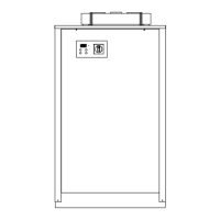
5.1 Control panel (SRC-- 150 --- SRC-- 200)
QS
HL
HLA
T0
QS Main disconnector switch (dryer ON---OFF)
HL On lamp (green, signals that dryer is operating)
HLA Alarm lamp (red, signals that dryer is in alarm)
T0
Dew point thermometer:
green = dewpoint ideal
red = dewpoint too high
blue = dewpoint too low