DESCRIPTION
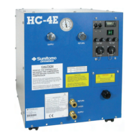
The components of the HC-4A Zephyr
®
Series Air-Cooled Compressor are identified
schematically in Figure 1. Figure 2 identifies front panel components. Features and functions
of individual components are described in the following paragraphs.
Components (See Figures 1, 2 and 3)
50/60 Hz Toggle Switch (HC-4A2 only): This switch is used to select different phasing circuits
for cold head operation at 50 Hz or 60 Hz.
Accessory Receptacle and Optional Remote On/Off Cable: The accessory receptacle
mounted on the front panel is a 14-socket connector for supplying remote on/off capability. The
remote on/off cable is available as an option.
Circuit Breaker: A panel-mounted, 20 ampere, circuit breaker in the main power supply
protects the compressor from electrical overload.
Cold Head Receptacle and Optional Cables: A 28-socket receptacle mounted on the front
panel and a cold head cable supply electrical power from the compressor to the cold head. The
HC-4A compressor can be supplied with cold head cables for operating a DE-202, DE-204SL,
M204S or CH204S Cold Head. The HC-4A2 compressor can be supplied with a cold head
cable for operating an RDK-101 series cold head.
Compressor Power Cord: Terminating with a 3-prong, NEMA L6-20P plug, the power cord
supplies electrical power to the compressor.
Elapsed Time Meter: The battery-operated LCD digital display, elapsed time meter shows the
compressor’s cumulative running time in hours up to a total of 99,999 hours.
AVOID INJURY. The compressor’s elapsed time meter contains a lithium
battery. Do not remove the battery. Do not recharge, disassemble, mutilate, wet
or dispose of the meter in fire. Contact local environmental authorities for proper
disposal of the lithium battery.
Electrical Chassis: The electrical chassis contains electrical components and connections and
distributes power to all system circuits. The wire terminals are accessible by removing a cover
from the front panel of the compressor. Components are accessible by removing the right side
cover from the compressor capsule.