V07-2014 Page 5 of 24 ©
Installation procedure:
Refer page 10 if restricted side room
1.
Ensure that the gates swing freely and that all existing latches/padbolts/Chains etc are disabled or
removed from the gate & Gate posts
2.
When using a 240v Unit [XP 100 or XP 100/300] the Master operator [the one containing the
Circuit Board] should be fitted to the Gate Post nearest the Power Supply.
Remove the cover, from the XP Operator [taking care that you DO NOT expose circuit board
to any moisture] to access the slotted fixing holes cut in the rear of the Chassis. Bend the
tabs out and bend them back against the rear of the chassis, in this position they act a
spacers allowing clearance for the cover[s] NOTE: [Do not remove these tabs – just bend
them out and fold them to the back] [Unless you are using the optional XP-MP Mounting
Plate]
3.
Position each unit on the gate post/pier/pillar[s]
The vertical position is found by locating the gate bracket. The Gate bracket is best placed where
there is adequate fixing on the gate and movement of the arms is unrestricted [See Fig. 2]
The XP Auto Gate Operator[s] may now be bolted in place.
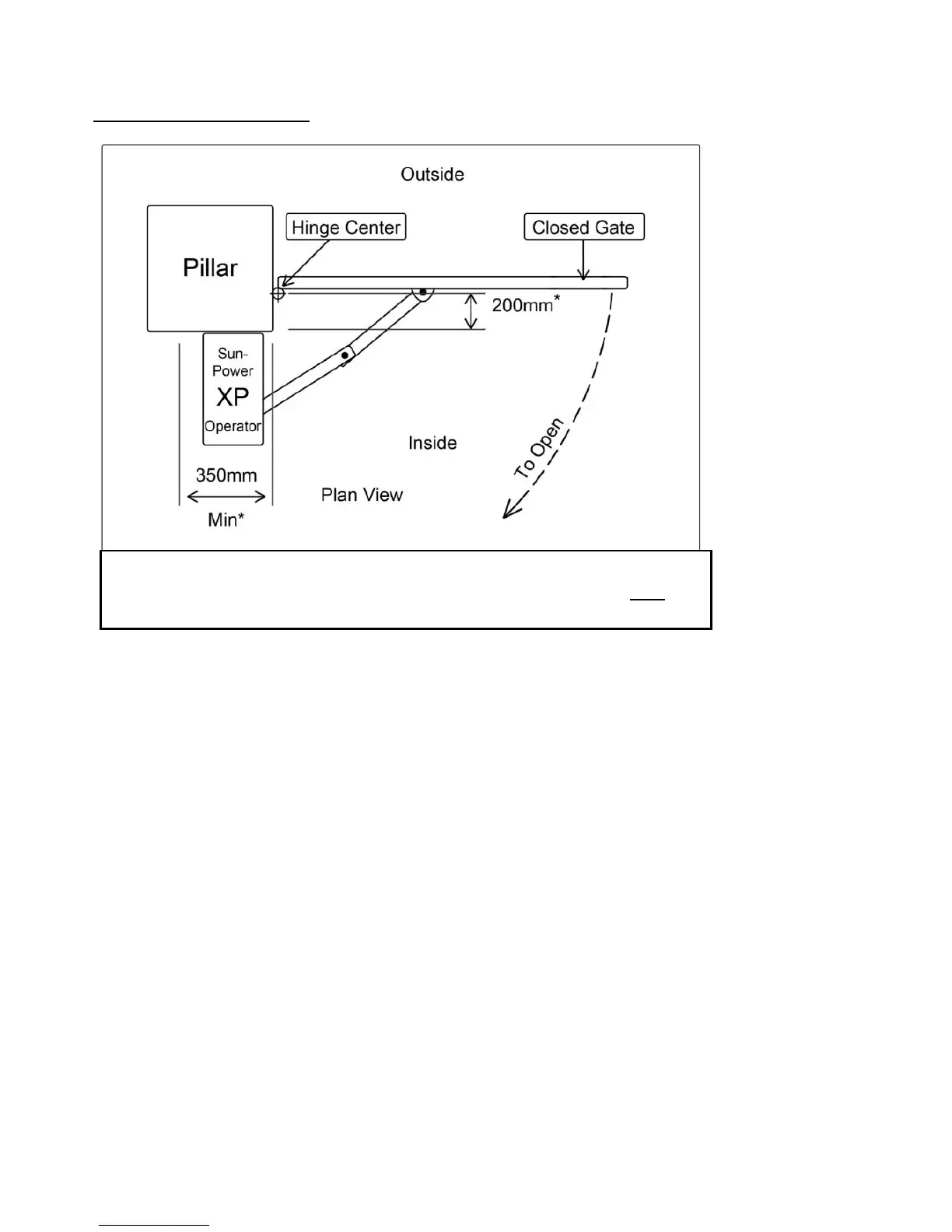
Fig 1. Standard Installation:
*Where the distance is greater than 200mm the Secondary arm may
need to be extended, contact Sun-Power if you need assistance.
 Loading...