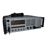
RT-9000C Hardware Supplement
Document No. 8128000602
Revision A (19 Mar 2007)
8-2
RT-9000 C
8.2 Installation
This section provides new or improved drawings used in the installation process. With noted exceptions, this
information applies to all RT-9000 transceiver models (RT-9000A, RT-9000B, and RT-9000C).
Note that the connections for Audio connector J5 are unique to the ISB-capable RT-9000C model
and must
be observed. The internal audio signal routing used in the RT-9000C has been altered to accommodate ISB
operation and is different from all previous RT-9000-series Transceivers. This connection scheme must be
used regardless whether ISB mode is used or not.
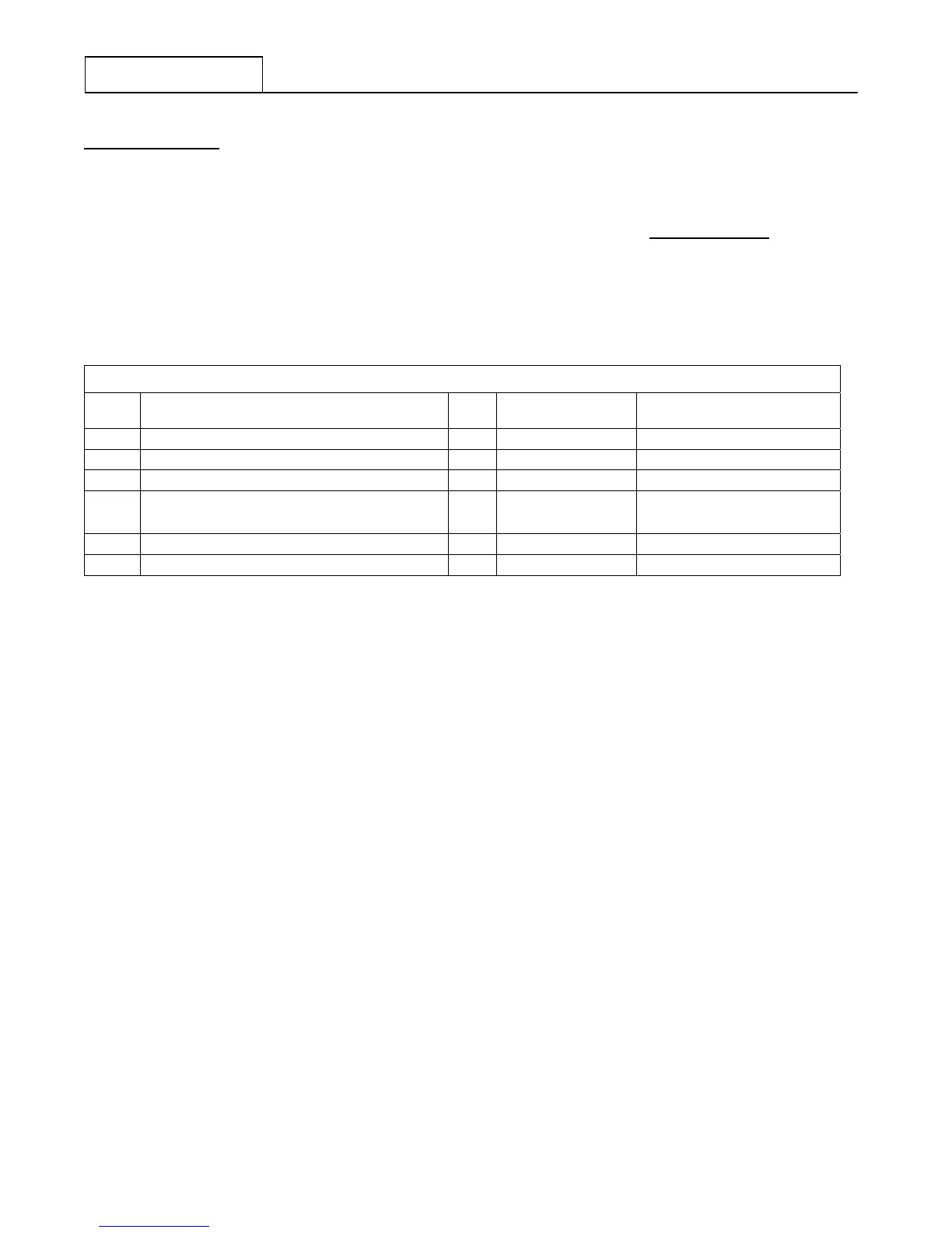
Refer to the following chart to indicate the application of these drawings.
RT-9000-Series Installation Drawing Application
Figure
No.
Subject
Page
Application Remarks
8.1 RT-9000C Outline Dimensions 8-3 - All models -
8.2 RT-9000C Rack Mounting Details 8-4 - All models -
8.3 RT-9000C Rear Panel Connector Locations 8-5 - All models -
8.4 RT-9000C J5 AUDIO Connector Details 8-6
RT-9000C unique
Unique Audio connections,
ISB-specific
8.5 RT-9000C J6 ACCESSORY Connector Details 8-7 - All models -
8.6 RT-9000C J8 REMOTE Connector Details 8-8 RT-9000B and later RS-485 no longer supported
 Loading...