RT-9000C Hardware Supplement
Document No. 8121000602
Revision A (19 Mar 2007)
8-7
RT-9000C
RT-9000 C ACCESSORY (J6) Connector Signals
Organized by Connector Pin No. Organized by Signal Name
Pin
No.
Signal Name
Input
Output
Notes Signal Name
Input
Output
Pin
No.
Notes
A + 28 V Tune Enable X Accessory Keyline Out X X
B Coupler Detect X Band 0 X h Low True
C Ready X Low True Band 1 X W Low True
D Fault X Low True Band 2 X j Low True
E Chan. bit 1 (2
0
) / Freq. (Ones) BCD 1 X Low True LSB Band 3 X V Low True
F Chan. bit 3 (2
2
) / Freq. (Ones) BCD 4 X Low True Band 4 X k Low True
G Chan. bit 5 (2
4
) / Freq. (Tens) BCD 1 X Low True Band 5 X U Low True
H Chan. bit 7 (2
6
) / Freq. (Tens) BCD 4 X Low True Band 6 X I Low True
J LPA Power Select X Low True Band 7 X T Low True
K LPA Reflected Power X Band 8 X S Low True
L Tune Command X Chan. bit 1 (2
0
) / Freq. (Ones) BCD 1 X E Low True LSB
M LPA ALC X Chan. bit 2 (2
1
) / Freq. (Ones) BCD 2 X a Low True
N LPA ACC X Chan. bit 3 (2
2
) / Freq. (Ones) BCD 4 X F Low True
P - Not Used - Chan. bit 4 (2
3
) / Freq. (Ones) BCD 8 X b Low True
R LPA Power Detect 1 X Chan. bit 5 (2
4
) / Freq. (Tens) BCD 1 X G Low True
S Band 8 X Low True Chan. bit 6 (2
5
) / Freq. (Tens) BCD 2 X n Low True
T Band 7 X Low True Chan. bit 7 (2
6
) / Freq. (Tens) BCD 4 X H Low True
U Band 5 X Low True Chan. bit 8 (2
7
) / Freq. (Tens) BCD 8 X c Low True MSB
V Band 3 X Low True Coupler Detect X B
W Band 1 X Low True Fault X D Low True
X Accessory Keyline Out X LPA ACC X N
Y LPA Detect X LPA ALC X M
Z Tuning X Low True LPA Detect X Y
a Chan. bit 2 (2
1
) / Freq. (Ones) BCD 2 X Low True LPA Forward Power X p
b Chan. bit 4 (2
3
) / Freq. (Ones) BCD 8 X Low True LPA On X d
c Chan. bit 8 (2
7
) / Freq. (Tens) BCD 8 X Low True MSB LPA Power Select X J
d LPA On X LPA Power Detect 1 X R
e - Not Used - LPA Reflected Power X K
f - Not Used - Ready X C Low True
g LPA Power Detect 2 X Tune Command X L
h Band 0 X Low True Tuning X Z Low True
i Band 6 X Low True + 28 V Tune Enable X A
j Band 2 X Low True + 28 V X r
k Band 4 X Low True - Not Used - e
m Ground - Not Used - f
n Chan. bit 6 (2
5
) / Freq. (Tens) BCD 2 X LPA Power Detect 2 X g
p LPA Forward Power X Ground m
q - Not Used - - Not Used - q
r + 28 V X - Not Used - P
N
P
M
W
R
U
S
V
T
E
J
A
H
B
G
C
F
D
LK
k
rm
X
p
i
Y
j
h
f
b
Z
e
g
c
a
n q
d
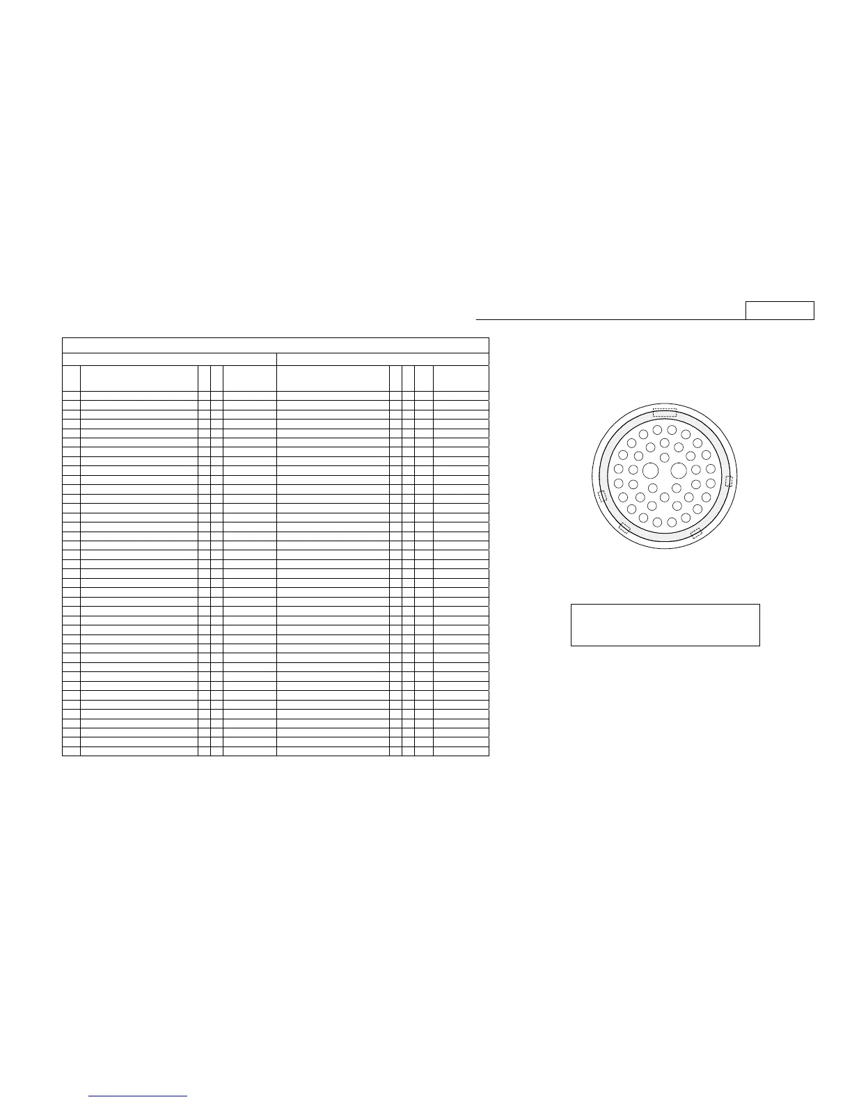
Notes:
1. Figure shows the mating connector that connects to ACCESSORY
connector (J6) located on RT-9000 C rear panel.
2. Termination end (or backside) of this mating connector is shown.
Figure 8.5 RT-9000C J6 ACCESSORY
Connector Details
 Loading...