SERVICE BULLETIN NO. 18
INSTRUCTIONS FOR SERVICING SUNBEAM MIXMASTER
MODEL 3 AUTOMATIC
(See Model Number Stamped on Bottom of Mixmaster Base)
Revised May 14, 1949
The Model 3 Automatic Mixmaster motor is controlled by an air governor that
operates on the following principle: A fan draws air into the motor housing
through the grille on the front, carries it past the armature and field coils, on
through the governor control, and delivers it out the back of the motor. Between
the fan and the air vent is a Bakelite disc that closes the back or the motor
housing. In the center or the disc a rectangular opening is placed, then across
the opening a thin blue steel shutter plate, or diaphragm is fitted with one edge
fixed to the Bakelite disc. A contact breaker point is riveted on the diaphragm.
Directly opposite another breaker point is attached to an arm.
As the air is pulled through the motor it pushes back the diaphragm to provide an
opening for the air to flow through and this action breaks the current flow
through the governor contact points. The amount or air pressure required to open
the diaphragm depends upon the resistance of the diaphragm to the air. To control
this resistance, tension is applied through the contact breaker point fitted on
an arm (this breaker point will be celled the Fixed
Contact throughout the
remainder of this bulletin, because the position of that contact point remains
fixed for any particular speed, its position being determined by the setting of
the switch knob).
When you turn the switch knob at the back of the motor you increase or decrease
the tension on the diaphragm by moving the arm slightly backward or forward. With
the switch knob turned to the lower speeds the tension against the diaphragm is
very light; the diaphragm opens easily, thereby breaking the current quickly. But
when the knob is turned to the higher speeds the arm applies more tension on the
diaphragm and a greater air pressure is required to open it and break the
current. Thus by adjusting the tension on the diaphragm and by alternately making
and breaking the current flow at a very rapid rate the governor maintains a
constant motor speed under all load and nominal voltage variations.
A condenser and resistor fitted on the Bakelite governor disc are shunted across
the governor breaker points to give the points long life and to reduce radio
interference. The resistor also smoothes out the operation of the motor by
allowing a small fraction of the current to flow through the motor while the
breaker points are open momentarily. A second filter condenser is fitted in the
lower part of the motor housing to reduce and eliminate radio interference.
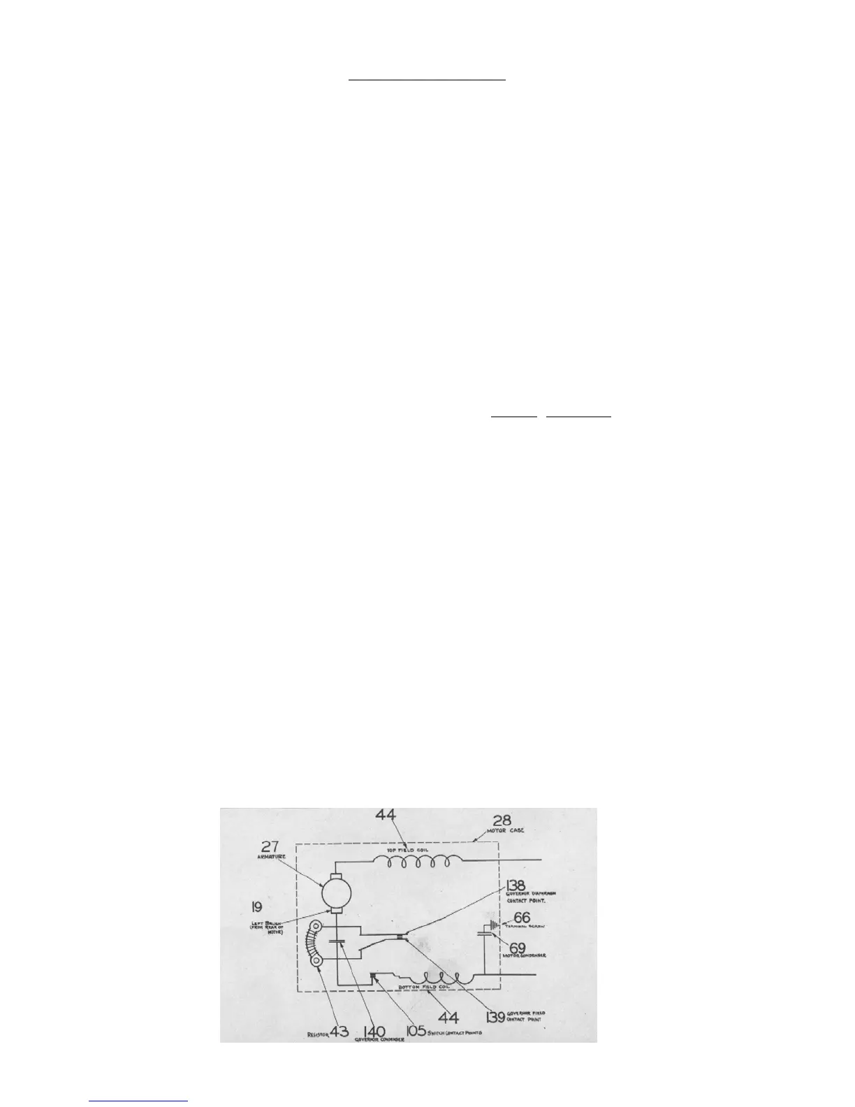
Wiring Diagram Model 3 Automatic Mixmaster