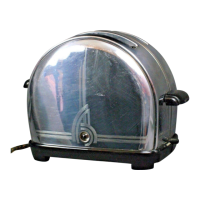
ton (63)which isattached to the bottom~moun.ting plate (II),: i~hen the ’parts".
are" aligned in the proper manner, insert the shoulder screws’(lOA) and lock
washers (lOB) through the~upper parallel bars into
~
the upper shaft assembly (9)..
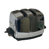
The lowe’r .shaft assembly (lO)°is mounted underneath .the upper shaft assembly
¯ through two. extruded holes in the element frame assembly~ (1), "The movable
switch contacts (36B) face toward the stationary contact .points (2)~ The
lower parallel bars are raised directly opposite the lower’ shaft ends and
the shoulder screws (IOA) and lock washer~ (lOB)inserted. When all four
Shoulder. screws are in position, raise and l~wer the rack assembly (56) to
see
that it. operates freely.
":
-.It may be necessary to .adjust relation between pawls
(56) if, when ’rack is lowered, ejector lever ~(35) does’ not move.the.’cor_.r.e_q.t .........
.......... d-is~ance- to--eng~ge -in- p~w1--(5~j .... It-’ ~6~d-~-5~
~
~c-~s-s~-%-0 -~-~ these
~arts and ejector~lever (35) should not be bent. If pawl support is found
~. : bent, it may be
*
straightened so that it forms a right angle with element
¯
frame. Raise or lower the round rod on which cushioning cylinder is mounted
to increase~ or decrease throw of ejector lever (35) and switch bracket (3~)¯
Using long-nose pliers, grasp flat metal ~f upper rack near point iwhere it
is riveted to ends of round rod and twist slightly in direction required to
move round rod up ordown. Twist eash end the same amount to’ k~ep rod lev-
"’ elo .It will be found that a slight upward twist near each end of the rod
will increase the throw
of
lever (35) considerably.
(!i..~. 3-Ho SwitchSpring (23) and.Ejector Spring (21). -The switch spring is fitted.
i~ii~ . between:the notched projections on’switbh lever (36) and slot in the ele-
ment ’frame (1) directly behind the’upper shaft. The ejector spring (21)
I
is fitted between the adjusting screw (32) projecting through a slot’in:
the bottom mo6nting plate (ll) and the top of ejector lever (35).’ Tofit
this spring, remove the .adjustment nut (21A)from adjusting screw (32) .and
loop the end of the spring (21) through the screw. Lower this through the
slot in the mounting plate and fit adjustment nut (21A)~ With the end of
a small screw drlver~. raise the other end of the spring to the hole in the
ejector lever (35).
3-I. Switch Locking Lever (3~)~ - The switch lockihg l~ver (33) may be replaced
.as follows: Torsion spring (33A) should be fitted about pivoting pin so’
that the switch lever (33) moves downward inside switch arm (36A). ’ Insert
the pivoting pin of the lever into its proper location on the.underside 5f
the bottom mounting plate. Bend the lugs with th~ bearing holes up to nor-
mal position to locate the locking lever. ’When the plastic bas.e (16).’has.
been put on .the mounting plate, examine the Switch locking lever for clear-
ance with the thermostat blade (~7)’ at the reflector end of the toaster,
It is important that the switch locking lever be from 3/6~: t6 3/32 inch a-
bove the top of the casting uoon which the thermostat blade is mounted.
This is checked after fitting plastic base (16).by inserting gauge T20~9i-l:
in position where thermostat bracket (50) fits. Theend of the lever should
enter but not pass the step i~ the gauge. The test should be made with mov-
¯ "able
hahdle (15) lower~d."~’ ’ " ’
(
3-J. Cut-Out’Rod (17). - When.the cut-outrod is in place, check its effect on
the switch locking lever (33)’by.r~ising and lowering racM. assembly (~6)~
As the rack assembly moves upward, the cut-out rod will operate s.witch .lock-
ing lever (33) and open the circuit.
"’ ..~