SUNERGY USA WORKS LLC
conductor. The grounding conductor or strap may be copper, copper alloy, or other material
acceptable for use as an electrical conductor per respective National Electrical Codes. The
grounding conductor must then make a connection to earth using a suitable earth ground
electrode.
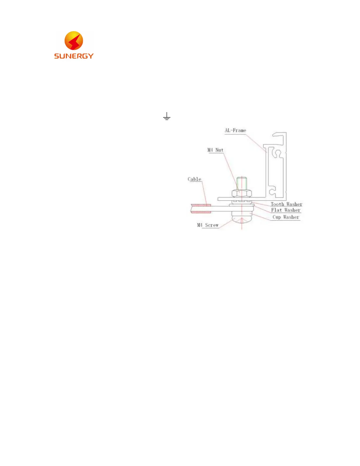
Attach a separate conductor as grounding wire to one
of the 4mm diameter grounding marked
on the module frame with a set of M4 screw, cup washer,
flat washer, tooth washer, and M4 nut. This is to ensure
positive electrical contact with the frame.
Schematic drawing
for SPV module grounding
11. INSTALLATION WORK
Using corrosion-proof screws (M8) on the existing installing holes in the module frame.
11.1 Secure the supporting structure according to the mounting holes in the frame of each
module.
11.2 The module frame must be attached to a supporting structure using M8 stainless steel
hardware together with spring washers and flat washers in eight places symmetrical on
the module.
11.3 Clearance between the module frame and mounting surface may be required to prevent
the junction box from touching the surface, and to circulate cooling air around the back
of the module.
11.4 Connecting the solar panels.
12. Connect each array according to the solar array connection examples.
12.1 The cable must not be bent or crushed on the direct exit of the cable screw joint include
connecter and junction box. A minimum bending radius R≥4×cable diameter must be
maintained. The cable must be routed in a way that tensile stress on the conductor or
connections is prevented. The cable must meet EN 50618.
12.2 There is a cable (+) and a cable (-) on the rear side of each solar panel. Connect the
waterproof connectors on these cables, making sure to push the connectors all the way
in.
 Loading...