User Manual 5 Electrical Installation
19
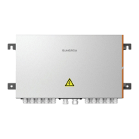
Figure 5-2 Aluminum wire connection diagram
Copper aluminum
transition terminal
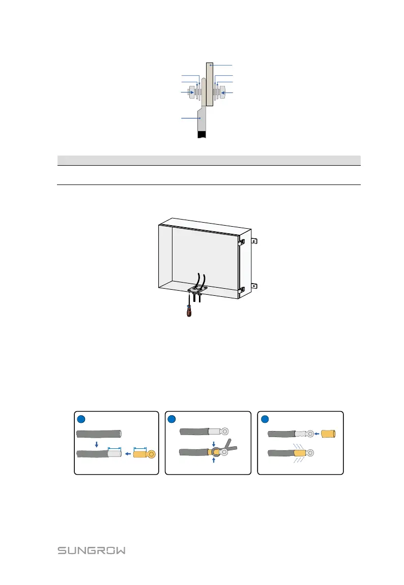
Step 5 Install the waterproof terminal assembly to the bottom of the combiner
box.
Wiring scheme 2
Step 1 Pass the cable with the wire designation "DC+" through the "INPUT
DC+" waterproof terminal, and reserve an appropriate length margin.
Step 2 Strip the protective layer and insulation layer of the cable to expose the
copper core part of the wire L≈25mm, crimp the cable to an appropriate
DT terminal, and put it into a heat shrink tube.
Step 3 Fix the crimped DT terminal to the input terminal.
For copper wire, the fixing method is as shown in the figure below, and the
tightening torque is 34~40N.m.