6
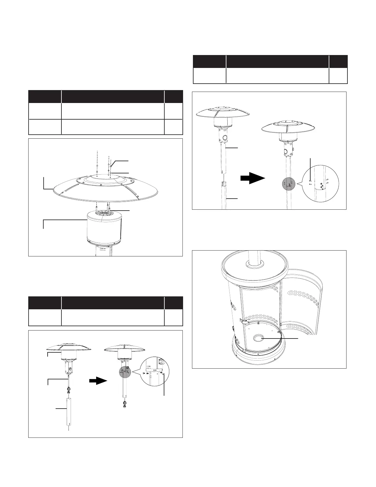
6. Attach the reector assembly to the burner assembly.
Place a plain washer (B) over the threaded end of each
reector stud (D) sticking out through reector assembly
and secure with cap nuts (C). Note: Do not overtighten
(Fig. 6).
Hardware Required
7. Insert the propane hose that is connected with the burner
assembly into the upper pole. Secure with 4 M6x14
hexagon socket head bolts (E) (Fig. 7)
Hardware Required
8. Connect the upper pole assembly with the lower pole
assembly as shown. Fix with 6 M5x12 pole screws (F)
(Fig. 8).
Hardware Required
9. Fill sand into the cylinder tank base through the hole in the
middle, as shown (Fig. 9).
NOTE: Purchase sand separately at your local garden
center or hardware store.
10. Insert the ends of the cylinder securing wire into the two
small holes on the tank base (Fig. 10).
ITEM DESCRIPTION QTY.
C
Cap nut (M6) 3
B
Plain Washer (6 mm) 3
Fig. 6
Reector
assembly
Plain washer
Burner
assembly
Cap nut
Reector stud
ITEM DESCRIPTION QTY.
E
Hexagon socket head bolt (M6x14) 4
Fig. 7
Hexagon socket
head bolt
(M6x14)
Burner
assembly
Propane
hose
Upper
pole
ITEM DESCRIPTION QTY.
F
Pole screw (M5x12) 6
Fig. 8
Upper pole
assembly
Lower pole
assembly
Pole screw
(M5x12)
Fig. 9
Fill the hole
with sand
until it's full.