SUNPOWER CORPORATION
Safety and Installation Instructions - Document 001-15497 Rev U
©September 2020 SunPower Corporation. All rights reserved. Specifications included in this manual are subject to change without notice.
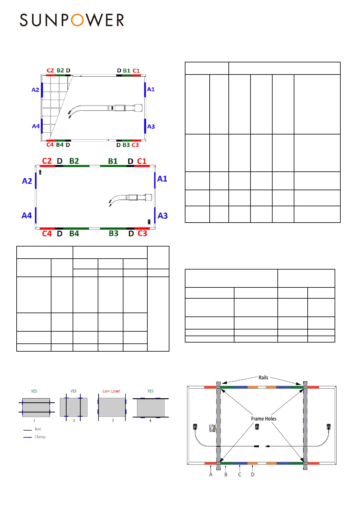
Figure 2: Mounting Zone locations for SunPower modules
For 96 cells, P-Series and 104c:
For 128 cells,P-Series and MAX5 Commercial:
Table 1: Approved module clamping/direct fixation zones
Module Configuration
Mounting zone distance from
corner in (mm)
1
Frame
holes
E
Module size
Frame
type
A B C
(1&2&3&4)
(1&2&3&4)
(1&2&3&4)
(1&2&3&4)
96 cells, 104
cells (MAX2 and
MAX3) and P3
BLK
G3
(Black)
Silver &
G4.1 &
G4.2 &
G4.3
50-350
150-380
50-150
As per
Drawing in
the Table 2
128 cells and
P19-COM
G4 &
G4.1 &
G4.2
50-350 408-880 50-375
P3-COM
G4.2 &
G4.3
50-350 408-833 50-375
MAX5-COM G4.2 50-350 296-796 50-296
D - There is a 20mm zone at 388-408mm from the corner where mounting is not
allowed due to the module stacking pin feature. Not applicable for all P19 Series, all P3
Series, 96 cells residential modules, all 104 cells and MAX5 modules.
1) No part of the module clamp may extend beyond this area.
Figure 3: Mounting Configurations
Configurations 1 and 2 show mounting with rail support, 3 and 4 show
mounting without rail support. In “With Rail Support” the rails
becomes conventional or rails transverse while “Without Rail
Support” becomes end mounted in long or short side. In the case
when the glass deflects it would not deflect in the rails for additional
support.
Table 1.2: Mounting Zone Design Load Ratings for Racking system
without rail support underneath the module. Refer to Configuration 3
and 4 in Fig.3
Module
Configuration
Wind (up & down) / Snow (down)
(units in Pa) (***)
Module
size
Frame
type
End
Mount
A
(1&2&3&4)
Frame
Holes
E
(1&2&3&4)
B
(1&2&3&4)
C
(1&2&3&4)
or B + C
(B
1&3
+C
2&4
or
B
2&4
+C
1&3
)
Or A + B
(A
1&3
+B
2&4
or
A
2&4
+B
1&3
)
Or A + C
(A
1&3
+C
2&4
or
A
2&4
+C
1&3
)
96 cells,
104 cells
(MAX2 and
MAX3) and
P3 BLK
G3
Black &
Silver &
G4.1 &
G4.2 &
G4.3
2400/
2400
(*)
2400/
5400
2400/
5400
2400/2400
128 cells,
P19-COM
G4 &
G4.1 &
G4.2
Not
applicable
(**)
2400/
5400
3600/
3600
2400/2400
P3-COM
G4.2 &
G4.3
1600/
1600
1600/
3600
2000/
2400
1600/ 1600
MAX5-
COM
G4.2
Not
applicable
(**)
2400/
5400
3600/
3600
1600/1600
(*): 5400Pa is allowed with clamps and mounting rails along the longer side of the frame
(**): 2400/2400Pa are allowed with clamps and mounting rails along the longer side of
the frame
For Rooftop application 1200/1200Pa is allowed with only clamps
(***) Safety factor of 1.5 included
Table 1.3: Mounting Zone Load Ratings for Racking system with rail
support. Refer to Configuration 1 and 2 in Fig.3
Module Configuration
Wind (up & down) /
Snow (down)
(units in Pa)
Module size Frame type B
(1&2&3&4)
C
(1&2&3&4)
96 cells, 104 cells
(MAX2 and MAX3) and
P3 BLK
G3 (Black &Silver) &
G4.1 & G4.2 & G4.3
2400 / 5400 2400 / 2400
128 cells and P-series
19-COM
G4 & G4.1 & G4.2 3600 / 5400 2400/ 3600
P3-COM G4.2 & G4.3 2000/2400 1600/ 1600
MAX5-COM G4.2 3600/3600 2800/2800
Figure 4: Mounting Zone Locations for Performance modules
For P3 and P5 UPP:
 Loading...