SUNPOWER CORPORATION
Safety and Installation Instructions - Document 001-14158 Rev AG
© 2020 SunPower Corporation. All rights reserved. Specifications included in these instructions are subject to change without notice. Page | 3
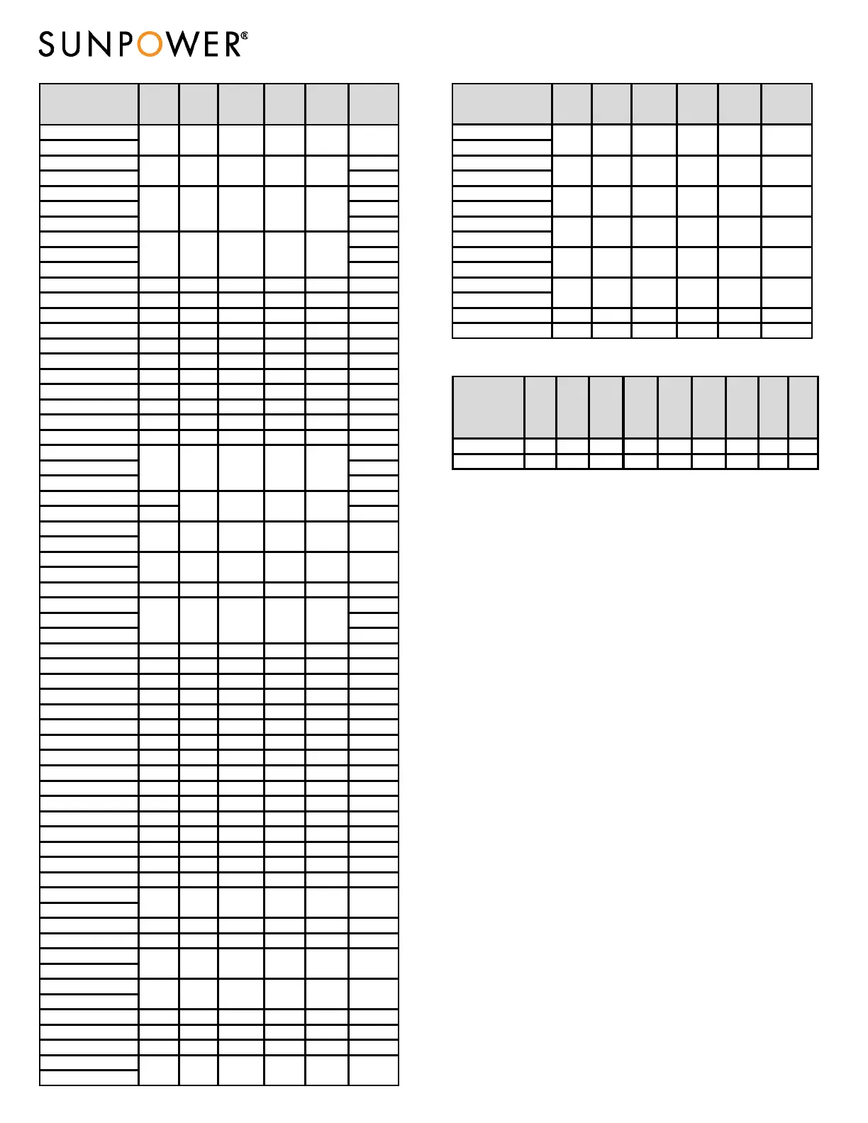
Module
Rated
Power (W)
Voltage at
Rated
Power
Vmpp (V)
Current at
Rated Power,
Impp (A)
Open
Circuit
Voltage
Voc (V)
Short Circuit
Current, Isc
(A)
Maximum
System
Voltage UL
Vmax (V)
SPR-X21-335
SPR-X21-335-BLK
SPR-X19-315-COM 1000
SPR-X19-315-BLK 600
SPR-X20-327-COM 1000
SPR-X20-327 600
SPR-X20-327-BLK 600
SPV-X19-310-COM 1000
SPR-X19-310 600
SPR-X19-310-BLK 600
SPR-X22-360-COM-MLSD 360 59.1 6.18 69.5 6.66 1000
SPR-X21-345-COM-MLSD 345 57.3 6.02 68.2 6.39 1000
SPR-X21-335-COM-MLSD 335 57.3 5.85 67.9 6.23 1000
SPR-X20-327-COM-MLSD 327 57.3 5.71 67.6 6.07 1000
SPR-E20-450-COM 450 72.9 6.18 86.5 6.65 1000
SPR-E20-445-COM 445 72.9 6.11 86.5 6.57 1000
SPR-E20-440-COM 440 72.9 6.04 86.5 6.5 1000
SPR-E20-435-COM 435 72.9 5.97 85.6 6.43 1000, 1500
SPR-E19-420-COM 420 72.9 5.77 85.6 6.20 1000
SPR-E19-410-COM 410 72.9 5.62 85.3 6.01 1000
SPR-E21-340-COM 340 54.7 6.21 64.9 6.71 1000
SPR-E20-327-BLK 600
SPR-E20-327 600
SPR-E20-327-COM 1000
SPR-E19-320 320 600
SPR-E19-320-COM 320 600
SPR-E19-315
SPR-E19-315-BLK
SPR-E19-310-COM
SPV-E19-310-COM
SPR-E18-305 305 54.7 5.58 64.2 5.96 600
SPR-E18-300-COM 1000
SPR-E18-300-BLK 600
SPR-E18-300 600
SPR-E18-295-COM 295 54.2 5.45 63.3 5.83 1000
SPR-E20-330-COM 330 54.7 6.04 64.9 6.52 1000
SPR-E20-330-COM-MLSD 330 54.7 6.04 64.9 6.52 1000
SPR-E20-327-COM-MLSD 327 54.7 5.98 64.8 6.46 1000
SPR-E19-320-COM-MLSD 320 54.7 5.86 64.7 6.24 1000
SPR-P19-400-COM 400 43.4 9.22 52.7 9.80 1500
SPR-P19-395-COM 395 43.2 9.14 52.5 9.72 1500
SPR-P19-390-COM 390 43.1 9.05 52.3 9.64 1500
SPR-P19-385-COM 385 42.8 8.99 52.0 9.58 1500
SPR-P19-380-COM 380 42.6 8.92 51.8 9.49 1500
SPR-P19-380-COM-MLSD 380 43.3 8.78 52.2 9.43 1500
SPR-P19-385-COM-MLSD 385 43.8 8.80 52.5 9.44 1500
SPR-P19-390-COM-MLSD 390 44.1 8.85 52.9 9.45 1500
SPR-P19-395-COM-MLSD 395 44.4 8.90 53.4 9.47 1500
SPR-P19-400-COM-MLSD 400 44.8 8.93 53.6 9.5 1500
SPR-A430-COM 430 42.7 10.1 51.2 10.9 1500
SPR-A440-COM
SPR-A440-COM-MLSD
SPR-A450-COM 450 44.0 10.2 51.9 11.0 1500
SPR-A450-COM 450 44.0 10.2 51.9 11.0 1500
SPR-A390
SPR-A390-BLK
SPR-A400
SPR-A400-BLK
SPR-A410 410 40.0 10.2 48.2 10.9 1000
SPR-A415 415 40.3 10.3 48.2 10.9 1000
SPR-A420 420 40.5 10.4 48.2 10.9 1000
SPR-MAX2-360
SPR-MAX2-360-COM
335 57.3 5.85 67.9 6.23 600
400 39.5 10.1 48.1 10.9 1000
390 39.0 10.0 48.0 10.8 1000
440 43.4 10.2 51.6 10.9 1500
1000
327 54.7 5.98 64.8
54.7
54.7 5.67 64.4 6.05
5.87
5.82
5.86 64.7 6.24
310
6.46
310 57.3 5.41
6.07
67.2
300 54.7 5.49 64.0
327 57.3 5.71 67.6
315 54.7 5.76 64.6 6.14 600
360 59.1 6.09 70.6 6.50 1000
315 57.3 5.50 67.3 5.9
Module
Rated
Power (W)
Voltage at
Rated
Power
Vmpp (V)
Current at
Rated Power,
Impp (A)
Open
Circuit
Voltage
Voc (V)
Short Circuit
Current, Isc
(A)
Maximum
System
Voltage UL
Vmax (V)
SPR-MAX2-350
SPR-MAX2-350-COM
SPR-MAX2-340
SPR-MAX2-340-COM
SPR-MAX3-400
SPR-MAX3-400-COM
SPR-MAX3-395-COM
SPR-MAX3-395
SPR-MAX3-390
SPR-MAX3-390-COM
SPR-MAX3-370
SPR-MAX3-370-COM
SPR-MAX3-375-BLK 375 62.5 6.00 74.9 6.52 1000
SPR-MAX3-355-BLK 355 59.8 5.94 74.3 6.49 1000
350 57.9 6.05 70.3 6.48 1000
400 65.8 6.08 75.6 6.6 1000
370 61.8 5.99 74.7 6.52
1000
1000
1000
6.55390 64.5 6.05
6.56
75.3
395 65.1 6.07 75.4
340 56.6 6.00 70.0 6.46 1000
UL 61730 Certified Models
Module
Rated
Power
(W)
+5/-0%
Voltage
at Rated
Power
Vmpp
(V)
Current
at Rated
Power,
Impp (A)
Open
Circuit
Voltage
Voc (V)
+/-3%
Short
Circuit
Current,
Isc (A)
+/-3%
Current
Temp.
Coeff.
%/°C
Voltage
Temp.
Coeff.
%/°C
Power
Temp.
Coeff.
%/°C
System
Safety
Class
SPR-A400-BLK 400 39.5 10.1 48.1 10.9 0.060 -0.239 -0.30 II
SPR-A390-BLK 390 39.0 10.0 48.0 10.9 0.060 -0.239 -0.30 II
4.0 Electrical Connections and System Monitoring
Modules may be connected in series or parallel to achieve the desired electrical
output provided certain conditions are met.
SunPower recommends using the same brand connector in a given PV system.
Currently approved compatible connectors found on SunPower modules are:
Tyco Solarlok PV4 and PV4S, Yukita (YS-254/YS-255), Multi-Contact MC4
(PVKBT4/6II, PVKST4/6II) and Staubli Electrical Connectors (PVKST4/6II-UR,
PVKBT4/6II-UR). SunPower warrants the connectors delivered on SunPower
supplied modules and harnesses as being compatible.
4.1 Equipment Grounding
To reduce the possibility of electrical shock, ground the frame of the module or
array per NEC before wiring the circuit. In order to install in accordance with their
UL Listing, SunPower modules must be grounded using grounding hardware that
meets requirements for grounding systems in UL 467, UL 1703, or UL 1741; on
anodized aluminum frames. SunPower recommends using one of the following
methods of grounding the module frame. In addition, to avoid corrosion due to
the use of dissimilar metals SunPower recommends stainless steel between
copper and aluminum. For the Generation 5 (G5) frame, only methods 1 and 2
apply. A-Series -BLK modules must be installed with the Ground Lug Assembly of
the Invisimount mounting system using the Ilsco GBL-4DBT grounding lug
tightened to a torque of 85 in-lbs to bond the module frame to the rail. The rails
used for bonding must be part of the system’s ground path.
1) Attach a lay-in lug (Ilsco GBL-4DBT, Burndy CL50-DB-T or Tyco Solklip 1954381-
2) to one of the grounding holes on the module frame, and attach the
ground conductor to the lug. Use stainless steel hardware (bolt, washers,
and nut). Use an external-tooth star washer between the lug and the
module frame in order to pierce the anodizing and establish electrical
contact with the aluminum frame. The assembly must end with a nut that’s
torqued to 20–25 in-lb (for a #10-32 bolt). A lock washer or other locking
mechanism is required to maintain tension between the bolt and the
assembly. The conductor must be attached to the ground lug using the lug’s
set screw. Refer to NEC 690.
2) SunPower modules may also be grounded through the use of SunPower IFF
clips which are UL Listed (1703 and 1741). IFF clip torque value is 35–45 in-
lbs for a 1/4-20 or M6 bolt, but may be higher in specific applications.
When using IFF clips, the module mounting system must be grounded as
per NEC 250.
Note: Method 3 is evaluated to UL 1703 by ETL. As such, the use of these devices
is not considered part of the UL Listing of these modules.
 Loading...