MAXEON SOLAR TECHNOLOGIES, LTD.
Safety and Installation Instructions - Document 001-15497 Rev.AA
©June 2023 Maxeon Solar Technologies, Ltd. All rights reserved. Specifications included in this manual are subject to change without notice.
2 Test loads are for informaon purposes only, design loads should be considered for the project design.
3 Design Load considers 1.5 Factor of Safety, Test load = Design load x 1.5. Product Warranty covers only design
load values. The design loads listed in this table supersede all other loads that may be defined by other
pares, unless there is a formal authorizaon by Maxeon.
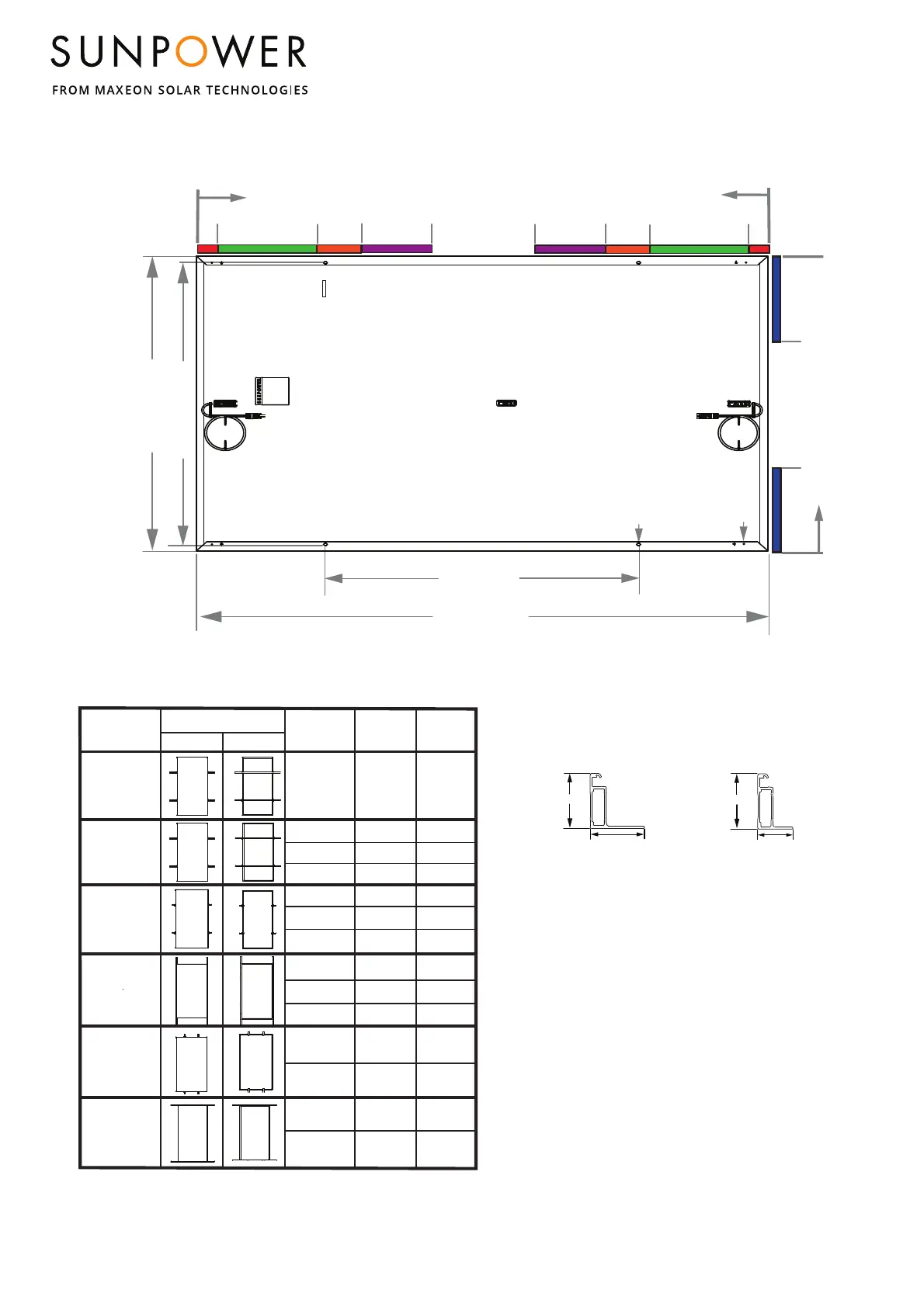
GEN 4.4 FRAME PROFILE
A - Ground Holes (4X Ø 4.2mm)
B - Mounng Holes (4X 9mm (W) x 14mm (L), R4.5mm)
SunPower Performance 6 Residenal and Commercial Solar Panel
(SPR-P6-XXX-BLK, SPR-P6-XXX-COM-XS)
1086 mm
1808 mm
0
B
SIDE FRAME PROFILE
END FRAME PROFILE
0
321
1100 mm
502
402
0
0
50
754
A
1038 mm
1 In the cases where hybrid mounng is necessary (combinaon of long and short side mounng), the lowest
design load values should be considered as allowable design load.
321
4 Boom flange mounng
502
402
50
754
30 mm
33 mm
30 mm
24 mm
Measurement Tolerances are +/-3mm for the Length and Width of the module.
5 Range indicates posioning of the clamp and not the rails
Mounng
Configuraon
Descripon
Mounng Configuraon Diagram
Front View
Back View
Mounng Zone
Locaons
(distance from corner
in mm)
50- 402
Long Side Mounng,
Rails Perpedincular
to Mounng
Frame
Long Side Mounng,
Rails Parallel to
Mounng Frame
Short Side Mounng,
Rails Parallel to
Mounng Frame
(End Mount)
502 - 754
+2000/-2400
+1400/-1800
+2000/-1800
+2700/-2000
+1333/-1600
+933/-1200
+1333/-1200
+1800/-1333
TOP CLAMPS
Short Side Mounng,
Point Supported
(End Mount)
402 - 502
+5400/-2400
+3600/-1600
Long Side Mounng,
Point Supported
0 - 221
+1600/-1400
+1067/-933
Test Loa d
Downward/Upward
(Pa)
Design Load
Downward/Upward
(Pa)
0 - 221
+1400/-1400
+933/-933
502 - 754
402 - 502
50 - 402
+2000/-2000
+1333/-1333
50 - 402
+2800/-1800
+1867/-1200
402 - 502
+2800/-1800
+1867/-1200
502 - 754
502 - 754
+2800/-1800
+1867/-1200
221 - 321
+1600/-1600
+1067/-1067
221 - 321
+1800/-1200
+1200/-800
Long Side Mounng,
Rails Perpedincular
to Mounng
Frame
217 - 617
+2700/-2000
+1800/-1333
 Loading...