Website: www.sunsynk.com E-mail: sales@globaltech-china.com 5
Standard Discharging Current
Max. Continuous Discharging Current
Max. Pulse Discharging Current
200A(2C, 30S, 25°C ± 2°C SOC≥40%)
0.5C CC to 57.6V, CV at 57.6V till current is 0.05C
Min. Operating Temperature (no derating)
Charging: 0°C / Discharging: -20°C
Max. Operating Temperature (no derating)
Charging: 50°C / Discharging: 55°C
SoC @ end of product line
Voltage Difference in each module
Inner Resistance of single Cell
0.34 ± 0.05mΩ (fresh cell 30 ~ 40% SoC)
440 x 530 x 132mm (not include connector, MSD and
other parts)
Greater than 10 years if used as per warranty terms
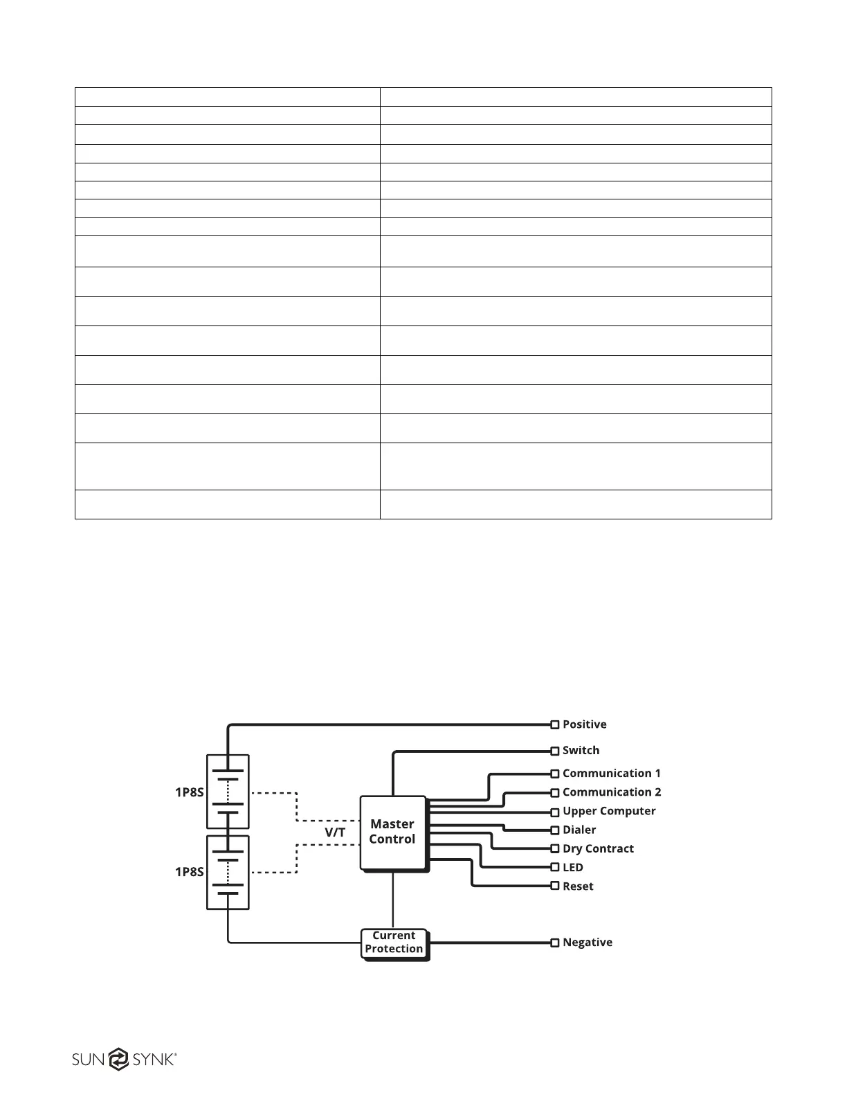
3.3. System Introduction
SSLB1 Energy Storage System is consisted of 2 sets of M025100-A modules manufactured by Sunsynk.
In each M025100-A, there are 8 pcs of 100 Ah LFP cell originated from CATL. The overall system also
provides standard communication port, i.e. CAN and RS485, to monitor the working status and
communicate with upper machine as well as the Power Conversion System (PCS) in front. The system
schematic drawing is presented in Figure 2.
Figure 2 - System schematics