EasyManua.ls Logo

Suntex CT-6110-POL User Manual

Default Icon
80 pages
To Next Page IconTo Next Page
Page #1 background imageLoading...
Page #1 background image
1
CT-6110-POL
Intelligent
Residual Chlorine
Transmitter
Operation
Manual

Table of Contents

Question and Answer IconNeed help?

Do you have a question about the Suntex CT-6110-POL and is the answer not in the manual?

Suntex CT-6110-POL Specifications

General IconGeneral
BrandSuntex
ModelCT-6110-POL
CategoryTransmitter
LanguageEnglish

Summary

Precautions for Installation

Brief Instruction

Index of Keypad

Details the functions of the instrument's physical buttons for navigation and operation.

Selection of Set-up Items

Describes various setup parameters like Mode, Span Adj., Polar. Volt, Polarogram, pH, and Temperature.

Brief Instruction (continued)

Motor

Explains motor settings for activation and water sample level detection.

Relay 1 / Relay 2

Details settings for alarm control and Hi/Lo points for relays.

Cln/Auto Zero

Covers automatic wash/auto zero time settings and duration.

Analog / Clock / RS-485

Settings for current output, date/time, and serial communication.

Black-light / Contrast / Digital Filter

Configuration for display brightness, contrast, and data averaging.

Logbook / Return / Code / Language

Options for event recording, auto-return, security codes, and language selection.

Description of Calibration Settings

Index of Keypad

Details the functions of the instrument's physical buttons for calibration navigation.

Selection of Calibration Items

Describes calibration options like Free Cl2, pH, Motor, Return, and Code.

1. Specifications

1.1 Specifications

Lists main technical specifications of the transmitter including measuring modes, ranges, and resolution.

1. Specifications (continued)

Performance

Details repeatability, linearity, accuracy, and response time of the instrument.

Other Specifications

Covers piping, sample conditions, environment, power, and dimensions.

1.2 Product Model and Spare Part Order Number

1.3 Measurement Principle

2. Assembly and Installation

2.1 Illustration of Overall Structure

Provides a detailed diagram of the transmitter's physical components and their assembly.

2. Assembly and Installation (continued)

Wiring of Residual Chlorine Electrode and Temperature Probe

Shows terminal connections for sensor wiring and temperature probe.

Installation of Cable Gland

Step-by-step guide for installing a cable gland for secure wiring connections.

2.2 Installation Dimensions and Combinations

2.2.1 Installation Dimensions

Displays overall dimensions and required clearance for proper installation.

2.2 Installation Dimensions and Combinations (continued)

2.2.2 Combination Types

Illustrates different ways to configure the transmitter with the support plate.

2.3 Illustration of Flow Configuration

2.3.1 Piping of Flow-through Chamber

Shows how to assemble couplings for the flow-through chamber.

2.3.2 Piping of Flow-through Chamber (When install with a pH sensor)

Details piping for the flow-through chamber when a pH sensor is included.

2.3 Illustration of Flow Configuration (continued)

2.3.3 External Piping Configuration

Provides reference diagrams for general and auto-zero calibration piping configurations.

3. Overview of Residual Chlorine Transmitter CT-6110-POL

3.1 Illustration of Rear Panel

Shows the terminal connections on the rear panel of the transmitter.

3.2 Illustration of Terminal Function

Diagrams the function of each terminal connection for power, sensors, and outputs.

3. Overview of Residual Chlorine Transmitter CT-6110-POL (continued)

3.3 Description of Terminal Function

Provides a detailed text description of each terminal's function and connection.

3.4 Illustration of Electrical Connection

4. Configuration

4.1 Illustration of Front Panel

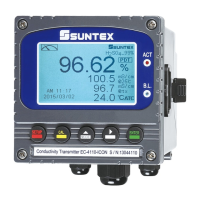
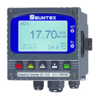
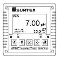
Displays the front panel of the transmitter, highlighting the screen and buttons.

4.2 Keypad

Explains the function of each key on the front panel for operation and navigation.

4.3 LED Indicators

Describes the meaning of the ACT and B.L. indicator LEDs.

5. Operation

5.1 Measurement Mode

Details the initial setup and operation after connecting power and turning on the instrument.

5.2 Set-up Menu

Instructions on how to enter and exit the instrument's set-up menu.

5.3 Calibration Menu

Instructions on how to enter and exit the calibration menu.

5.4 Shortcuts

Explains quick access functions using key combinations.

5.5 Default Value

Lists factory default settings for measurement display, calibration, and other parameters.

5.5 Default Value (continued)

5.5.2 Calibration Default Value

Lists factory default values specifically for calibration settings.

6. Measurement Display Mode

6.1 Text Mode

Describes the standard numerical display mode, showing measurement values and clock.

6.2 Real-Time Chart Mode

6.3 Trace Mode

6.4 Warning Symbols and Text

7. Settings

Block Diagram of Setting-Part 1

Visualizes the flow for configuring various instrument settings.

7. Settings (continued)

Block Diagram of Setting-Part 2

Continues the visual flow for configuring instrument settings.

7.1 Entry of Set-up Menu

7.2 Security Code of Settings

7.3 Language

7.4 Mode

7.5 Span Adj.

7.6 Polar. Volt

7.7 Polarogram

7.8 pH Function

7.9 Temperature

7.10 Motor

7.11 Relay 1

7.11 Relay 1 (continued)

7.12 Relay 2

7.12 Relay 2 (continued)

7.13 Clean/Auto Zero

7.14 Analog

7.14 Analog (continued)

7.15 Date/Time(Clock)

7.16 RS485 Communication

7.17 Sample Average of Measurements (Digital Filter)

7.18 Backlight Settings

7.19 Contrast Settings

7.20 Logbook

7.21 Return

8. Calibration

Block Diagram of Calibration

Visualizes the calibration process flow for different parameters.

8.1 Enter Calibration Setup Menu

8.2 Security Password of Calibration (Code)

8.3 Free Cl2 Calibration

8.3.1 Zero Point Calibration

Details the process for calibrating the zero offset of the free Cl2 electrode.

8.3 Free Cl2 Calibration (continued)

8.3.2 Span Calibration

Explains how to calibrate the span or relative slope of the free Cl2 electrode.

8.4 pH Calibration

8.4 pH Calibration (continued)

Definition of Calibration Parameter

Defines parameters like Asy (Zero point) and Slope used in calibration.

8.4.5 TECH, NIST Buffer Calibration

8.4.6 Any Calibration

8.5 Motor

8.6 Return

9. MODBUS Protocol and Instructions

9.1 Communication Connection

Details RS-485 communication connection methods, wiring, and notes.

9.2 MODBUS Address and Command Table

9.2 MODBUS Address and Command Table (continued)

9.2 MODBUS Address and Command Table (continued)

9.3 Modbus Example Description (ex: Function Code 03H)

10. Maintenance

10.1 Electrode

Explains electrode maintenance, self-cleaning, and replacement procedures for free Cl2 electrode.

10.1 Electrode (continued)

10.1.1 Free Cl2 Electrode

Details assembly steps for the free Cl2 electrode and sensor box, including replacement.

10.1 Electrode (continued)

10.1.2 pH Electrode

Provides cleaning methods for the pH electrode based on contamination types.

10.2 Motor and Drive Mechanism

10.2.1 Motor and Reducer

Troubleshooting guide for abnormal motor or reducer operation.

10.2.2 Timing Belt and Pulley

Troubleshooting guide for timing belt and pulley issues.

10.2 Motor and Drive Mechanism (continued)

10.2.3 Rotary Joint

Maintenance and troubleshooting for the rotary joint.

10.2.4 Bearing with Housing

Troubleshooting guide for bearing issues.

10.3 Flow-through Chamber

11. Error Messages (Error Code)

11. Error Messages (Error Code) (continued)

Appendix

Table 1 TECH Buffers

Provides temperature-dependent pH values for TECH standard buffers.

Appendix (continued)

Table 2 NIST Standard Buffers

Provides temperature-dependent pH values for NIST standard buffers.

Related product manuals