Do you have a question about the Suntex PC-300A Series and is the answer not in the manual?
Steps for installing the transmitter onto a panel.
Diagrams showing panel mounting dimensions and hole placement.
Instructions on preparing and connecting the coaxial cable.
Detailed assembly instructions for the electrode holder and junction box.
Instructions for installing the L-shaped electrode holder support base.
Diagrams and dimensions for the protective holder and support base.
Wiring diagram and terminal labels for a 2-wire system.
Wiring diagram and terminal labels for a 3-wire system.
Wiring diagram and terminal labels for a square junction box (2-wire).
Wiring diagram and terminal labels for a square junction box (3-wire).
Diagram of the rear panel connections and terminals.
Wiring diagram for electrical connections, including relays and external devices.
Diagrams and tables for wiring ATC probes and temperature compensation.
Diagrams for wall mounting the PH-300T transmitter.
Diagrams for pipe mounting the PH-300T transmitter.
Wiring diagram for PH-300T in a 2-wire system.
Wiring diagram for PH-300T in a 3-wire system.
Detailed steps for calibrating the pH electrode.
Detailed steps for calibrating the ORP electrode.
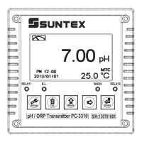
Diagram of the PC-310A front panel controls and indicators.
Explanations of POWER, STDBY, CALIB, and MODE buttons.
Explanation of the MODE button's functions and operations.
Explanation of the set point control knobs for PC-320A.
Detailed procedure for calibrating the pH electrode.
Procedure for inspecting and calibrating the ORP electrode.
How to set up and configure the RELAY control functions.
| Category | Transmitter |
|---|---|
| Series | PC-300A |
| Manufacturer | Suntex |
| Enclosure | IP65 |
| Protection Rating | IP65 |
| Accuracy | ±0.25% FS |
| Output Signal | 4-20 mA |
| Operating Temperature | -20 to 80°C |
| Process Connection | 1/2" NPT |
| Media Compatibility | Compatible with most liquids and gases |
| Zero and Span Adjustment | Manual adjustment |