Do you have a question about the Suntex EC-4110-I and is the answer not in the manual?
Essential safety advice for proper installation and operation of the transmitter.
Description of keypad functions and selection of various set-up items.
Explains the keypad for calibration and lists the available calibration items.
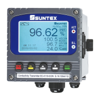
Comprehensive technical specifications for the EC-4110-I and EC-4110-ICON models.
Lists standard and optional accessories included with the product for installation.
Explains the inductive sensor technology and the conductivity measurement process.
Covers panel, wall, and pipe mounting procedures for the transmitter.
Visual guide for Sun Shield wall and pipe mounting, including screw fixings.
Illustrates the rear panel layout and describes the function of each terminal.
Provides detailed descriptions for each terminal, including sensor, power, and communication.
Details wire colors and descriptions for the 8-201-PFA-10 sensor assembly cable.
Diagram showing transmitter connections to external relays, cleaning devices, and dose feeders.
Shows wiring connections for extending the signal cable using a junction box.
Illustrates the front panel interface, including buttons and LED indicators.
Describes the function of each button on the transmitter's keypad.
Explains the meaning of the ACT and B.L. LED indicators on the device.
Instructions for entering measurement, set-up, and calibration menus.
Details shortcut operations and the factory default settings for the instrument.
Description of the normal digit display mode, showing main and auxiliary measurements.
Explains the real-time chart display for dynamic graphics of measured values.
Details the trace mode for recording and displaying trends of measured values over time.
Explains warning messages, symbols, and text displayed during operation or events.
Visual representation of the settings configuration flow for the instrument.
Instructions on how to enter the set-up menu to modify current settings.
Procedure for setting, activating, and managing security codes for configuration access.
Guide to selecting the system language from English, Traditional, or Simplified Chinese.
Setting up conductivity measurement with linear or non-linear temperature compensation.
Setting up absolute conductivity measurement without temperature compensation.
Configuring concentration measurement, solution type, and display mode for EC-4110-ICON.
Instructions for users to input their own concentration and conductivity data.
Setting up TDS measuring mode, units (ppm/ppt), and the TDS constant.
Procedure for entering and selecting the Salinity measuring mode.
Calibrating measurement values without altering the cell factor for field adjustments.
Guide to selecting PTC1000, PTC100, or NTC30K for auto/manual temperature compensation.
Setting reference temperature and selecting Linear, Non-Linear, or No compensation.
Configuring Relay 1 for high/low set-point alarms, hysteresis, and testing.
Configuring Relay 2 for high/low set-point alarms, hysteresis, and testing.
Setting up the automatic clean function timing, on/off times, and hysteresis.
Configuring analog output range and corresponding conductivity values.
Setting Modbus mode, baud rate, parity, stop bits, and device ID.
Instructions for setting the instrument's internal clock and date.
Configuring the digital filter to average samples for increased measurement stability.
Setting display brightness and sensitivity for backlight modes (ON, OFF, AUTO).
Adjusting the display contrast for optimal readability on a scale of -2 to 2.
Viewing and understanding transmitter event records and their Modbus codes.
Setting the instrument to automatically exit menus after a period of inactivity.
Visual flowchart of the calibration procedure, including Return, Code, Cell Constant, Std. Solution, and Zero.
Instructions for entering the calibration menu and displaying calibration information.
Procedure for activating and entering the security code for calibration mode.
Step-by-step guide for zero-point calibration of the inductive sensor in air.
Calibrating the cell constant using a tested solution and sensor signal cable values.
Procedure for calibrating with KCl standard solutions (111.8mS, 12.88mS, 1.413mS).
Procedure for calibrating with NaCl standard solutions (10.683mS, 251.3mS).
Details on RS-485 communication, including wiring, protection, and connection notes.
Table mapping Modbus logic addresses to transmitter parameters and data types.
Lists common error messages, their reasons, and recommended dispositions for resolution.
Illustrates the physical appearance and provides dimensional details of the 8-201-PFA sensor.
Instructions and diagrams for correct and incorrect flange installation, including immersion depth.
Step-by-step guide for flange installation and specifications for DN50 PL16.
Steps for installing the sensor into a Tee fitting using adaptor and hexagon nut.
Lists accessories required for immersion installation, including adaptors and protective holders.
Table of conductivity values for Potassium Chloride solutions at various temperatures.
Table of conductivity values for Sodium Chloride solutions at various temperatures.
| Brand | Suntex |
|---|---|
| Model | EC-4110-I |
| Category | Transmitter |
| Language | English |