DIRECT UPGRADE FOR EXISTING PROGRAMMERS
1.Switch off mains. Loosen 2 securing screws on
old programmer and unplug it.
2.Check existing wall-plate has been correctly
fitted. (See section,Fitting wall plate)
3.Plug SELECT programmer into wall-plate and
re-tighten screws. Switch on at mains.
4.Press RESET button located behind the flip-
down fascia panel. The status of the DIP switch
settings will be displayed. Pressing any button will
cause the display to go to time setting mode.
5.Set timing and programme as detailed in user
guide
FITTING WALL PLATE
1.Position the wall-plate (terminals along the top
edge) with 60mm(Min) clearance to its right,
25mm(Min) above, 90mm(Min) below. Ensure that
the supporting surface will fully cover the back of
the programmer.
2.Ideal location would be 1.4m above floor level,
easily accessible, reasonably lit and free from
condensation or temperature extremes.
3.Fix the wall-plate to a flush mounting single
conduit box type UA1(BS4662) using M3.5 x 14
bolts.
4.Ensure that the wiring to the wall-plate terminals
leads directly away from the terminals and is
completely enclosed within the wall-plate
aperture. Wire ends must be stripped and
screwed to the terminals, so that minimal bare
wire is showing.
5.If the unit is fitted to a metal surface, IT IS
ESSENTIAL that the metal be earthed. Do not use
a surface mounting box.
6.Ensure the mains supply is switched off, then
make wiring connections. No EARTH connection
is required, but ensure continuity of EARTH
throughout the system.
7.After wiring, plug unit into wall plate and tighten
the securing screws. Switch on at mains.
8.Press RESET button located behind the flip-
down fascia panel. The status of the DIP switch
settings will be displayed. Pressing any button will
cause the display to go to time setting mode.
9.Setting timing and programme as detailed in
user guide.
10.NEVER fit or remove the unit to a LIVE
wall-plate.
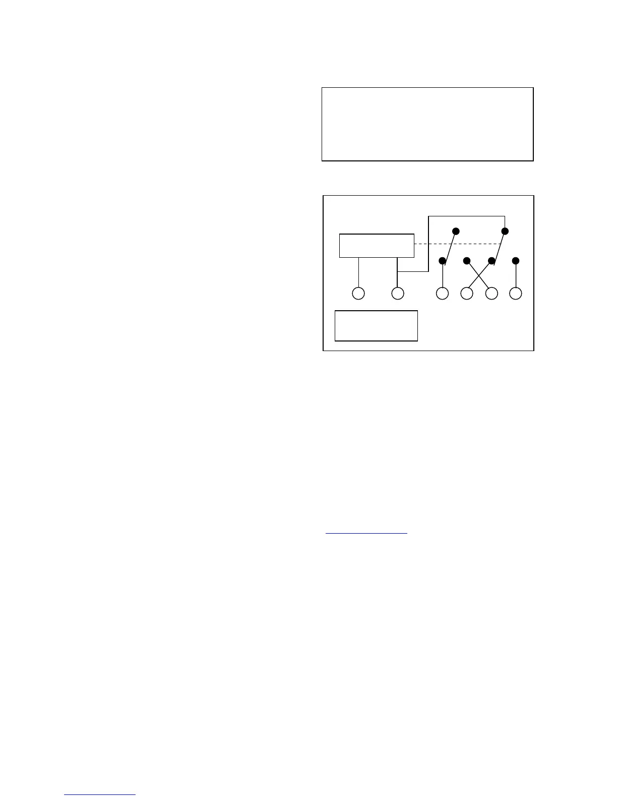
Programmer Internal Wiring Diagram
SUNVIC CONTROLS Ltd.
Bellshill Road
Uddingston
Glasgow
G71 6NP
Tel 01698 812944
Fax 01698 813637
Tech Helpline 01698 810945
Tech Help. Fax 01698 307437
WWW.sunvic.co.uk
In the interests of continuous product
improvement, Sunvic Controls reserve the right to
alter designs, specifications and materials, without
prior notice, and cannot accept liability for error.
Installation leaflet LE/497/0001 ISSUE 01 FEB 2003
DIRECT PLUG-IN REPLACEMENT FOR EXISTING PROGRAMMERS
N L 1 2 3 4
HW CH HW CH
OFF OFF ON ON
Electronics
Mains Fused
6Amps
This product complies with the essential requirements of
the following EC Directives:
Electro-magnetic compatibility directive
EMC 89/336/EEC (as amended by 91/263/EEC
And 92/31/EEC
Low Voltage directive
LVD 73/23/EEC;93/68/EEC
 Loading...