2
5
6
6
5
4
1
2
7
4
7
3
or
3
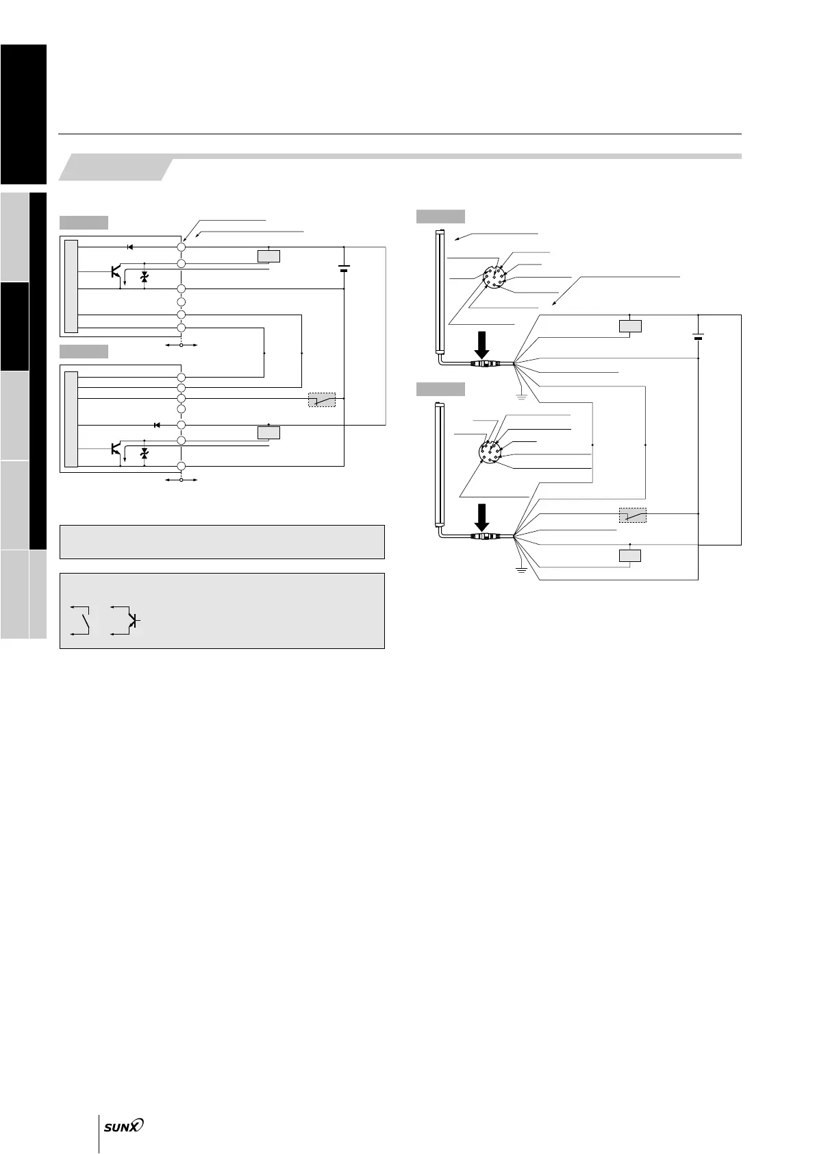
Sensor circuit
m1
Load
Emitter
Connector pin No.
Color code of mating cable
Sensor circuit
60 mA max.
(Brown)
V
(Pink) Alarm output
(Blue) 0 V
(Gray) Not connected
(Orange) Synchronization
(Orange / Black) Synchronization
Users’ circuitInternal circuit
200 mA max.
(Brown)
V
(Black) OSSD
(Gray) Test input (emission halt input)
(Orange) Synchronization
(Violet) Not connected
(Orange / Black)
Synchronization
(Blue) 0 V
Receiver
24 V DC
15 %
FSD
Note: Unused wires must be insulated to ensure that they do not come into
contact with wires already in use.
Non-voltage contact or NPN open-collector transistor
• Test input (emission halt input)
0 to
15 V: Emission (source current: 2 mA or less)
Open, or Vs1.5 V to Vs: Emission halt
(Note)
Users’ circuitInternal circuit
Note: Vs is the same voltage as the voltage of the power supply to be used.
m1
CAUTION
Use a safety relay unit or an equivalent safety control circuit for FSD.
F.G.
4
Not connected
Emitter
1
No use
7
0 V
2
V
6
Synchronization
5
Synchronization
3
Alarm output
8
Shield
(Note 3)
Connector pin No.
Color code of mating cable
Load
Brown
Pink
Blue
Gray (Not connected)
Orange
Orange / Black
24 V DC
15 %
Shield
(Note 3)
2
V
Receiver
8
Shield
(Note 3)
1
Not connected
7
0 V
3
OSSD
6
Synchronization
5
Synchronization
4
Test input
(emission halt input)
F.G.
Shield
(Note 3)
FSD
Orange / Black
Orange
Gray
Violet
(Not connected)
Brown
Black
Blue
m1
Unused wires must be insulated to ensure that they do not come
into contact with wires already in use.
Conductor cross-section area of lead wire of mating cable is 0.2 mm
2
(synchronization wire) and 0.3 mm
2
(exclude synchronization wire).
Be sure to connect the shield wire to the frame ground (F.G.).
Notes: 1)
2)
3)
 Loading...