Do you have a question about the Super X8DTL-iF and is the answer not in the manual?
Provides information for system integrators, technicians, and users.
Details the motherboard's support for Intel processors and QPI technology.
Outlines the structure of the manual and the content of each chapter.
Explains symbols used for proper installation and safety.
Provides contact details for Supermicro headquarters, Europe, and Asia-Pacific offices.
Details the items included in the retail box and congratulations on purchase.
Describes the Intel 5500 chipset features and its components.
Highlights unique features of the motherboard and its components.
Explains the system's health monitoring capabilities including voltage and fan status.
Explains Advanced Configuration and Power Interface features for power management.
Specifies power supply requirements and recommendations for the motherboard.
Describes the Super I/O capabilities and serial communication ports.
Details the Nuvoton WPCM450R Controller's functions, including BMC and KVM support.
Provides precautions for handling static-sensitive components to prevent damage.
Guides on how to install the motherboard into the chassis, including mounting.
Instructions for installing the CPU and its heatsink, including handling precautions.
Step-by-step guide for installing and removing RAM modules (DIMMs).
Details the front and back panel connectors and their locations.
Explains how to connect various power and other cables to the motherboard.
Describes how to configure motherboard settings using jumpers.
Explains the function and meaning of various onboard LEDs.
Details the connections for Serial ATA and SAS ports.
Outlines steps to diagnose and resolve common system issues before power on.
Guides users on steps to take before contacting technical support.
Addresses common user questions regarding memory support and BIOS updates.
Explains the process for returning products for warranty service.
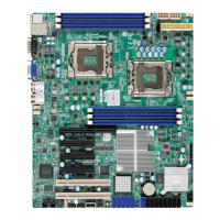
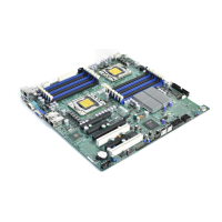
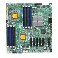
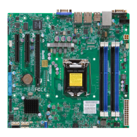
Visual representation of component and connector locations on the motherboard.
Provides a quick reference for jumpers, connectors, and onboard LEDs.
Details CPU support, memory slots, types, speeds, and capacity.
Describes the Intel 5500 chipset and available PCI/PCI-Express expansion slots.
Outlines BIOS features and system health monitoring capabilities.
Details ACPI power management and onboard I/O port functionalities.
Covers Wake-on-LAN, Console Redirection, and CD/Diskette utilities.
Provides the physical dimensions of the motherboard.
Highlights key features of the Intel 5500/5600 processors and the 5500 chipset.
Configures system behavior after AC power loss.
Details fan status monitoring and environmental temperature control mechanisms.
Explains system alerts via Supero Doctor III for resource status.
Defines ACPI, its role in power management, and the power button's functions.
Explains Wake-On-LAN and how external modem ringing can trigger system wake-up.
Details power supply requirements, including connector types and amperage.
Describes the Super I/O controller's support for drives and serial ports.
Details the Nuvoton WPCM450R Controller's functions, including BMC and KVM support.
Lists essential precautions for handling static-sensitive components and unpacking.
Guides on mounting the motherboard, listing tools and detailed installation steps.
Detailed steps for installing an LGA 1366 processor and its heatsink assembly.
Step-by-step guide for mounting the CPU heatsink securely.
Instructions for safely removing the CPU heatsink assembly.
Detailed procedure for inserting and removing RAM modules from slots.
Details memory support, including population and Registered ECC DDR3 DIMMs.
Details memory support for Unbuffered ECC/Non-ECC DDR3 DIMMs.
Specific memory support details for 1.5V and 1.35V Registered and Unbuffered DIMMs.
Identifies and defines the ports on the motherboard's rear I/O panel.
Details pin definitions for PS/2 keyboard and mouse connections.
Explains USB port locations and provides pin definitions for back and front panel connectors.
Describes serial port locations and pin definitions, and identifies the VGA connector.
Details onboard Ethernet ports and dedicated IPMI LAN, including pin definitions.
Visual layout of the front control panel header pins and their connections.
Specifies pin assignments for the NMI Button and Power LED indicators.
Specifies pin assignments for the HDD LED and Network Interface Card (NIC) LEDs.
Explains connections and states for overheat, fan fail, power fail, and UID LEDs.
Specifies pin assignments for the Power Fail LED.
Specifies pin assignments for the system Reset and Power buttons.
Details the 24-pin ATX and 8-pin CPU power connectors and their pin definitions.
Describes fan headers and the chassis intrusion header with their pin definitions.
Details the internal buzzer, power LED, and speaker connections.
Explains the Wake-On-LAN header and overheat/fan fail LED functionality.
Details SGPIO headers for serial link interfaces and the I-Button for RAID.
Describes the Power SMB (I2C) and IPMB headers for system monitoring.
Details UID switch/LEDs for system identification and the DOM Power connector.
Explains the Wake-On-Ring header for system wake-up via modem.
Explains jumper usage and how to enable/disable onboard GLAN ports.
Provides instructions for clearing CMOS and configuring the Watch Dog timer.
Details jumpers for I2C bus connection and enabling the onboard VGA.
Details jumpers for enabling SAS connections and selecting RAID modes.
Explains the status indications for GLAN and IPMI Dedicated LAN LEDs.
Explains the status indications for SAS and BMC Heartbeat LEDs.
Explains the status indications for the Onboard Power LED and Rear UID LED.
Details the Serial ATA ports and SAS ports, including their pin definitions and availability.
Lists steps to check before powering on the system.
Provides procedures to diagnose and resolve power and video issues.
Addresses causes for losing CMOS setup and troubleshooting memory errors.
Guides on technical support procedures and answers common questions about memory and BIOS.
Provides steps for BIOS updates and describes the contents of the included CD.
Explains the process for returning products for warranty service.
Introduces the AMI BIOS Setup Utility, its navigation, and how to change configuration data.
Details accessing the BIOS setup and the system overview screen.
Allows modification of the system's time and date settings.
Displays detailed processor and system memory information.
Configures boot options, Num-Lock, PS/2 mouse support, and other basic settings.
Configures error handling, power management, interrupt capture, and RTC alarms.
Allows configuration of CPU details, ratio, clock spread spectrum, and hardware prefetcher.
Configures cache prefetch, virtualization, SMT, processor cores, and EIST technology.
Configures TurboBoost, C-States, DCA technology, and related power/performance features.
Configures QuickPath Interconnect speed, frequency, and memory frequency.
Configures memory modes, error scrubbing, interleave settings, and virtualization support.
Configures I/O acceleration, USB ports, power management, and legacy USB support.
Configures SATA#1 and SATA#2 modes, drive types, and RAID/AHCI options.
Configures IDE drive types, LBA, block transfer, PIO, and DMA modes.
Details various SWDMA, MWDMA, and UDMA modes for SATA drives.
Configures NVRAM, PCI slots, Option ROMs for LAN/SAS, and boot graphics priority.
Configures serial port addresses, attributes, and Console Redirection settings.
Configures CPU overheat alarm settings and provides warnings for system safety.
Displays CPU temperatures and allows selection of fan speed control modes.
Displays various system voltage readings for monitoring.
Configures ACPI power management and Trusted Platform Module support.
Displays IPMI firmware revision, BMC status, and allows viewing BMC System Event Log.
Configures IPMI LAN adapter settings, including IP address source.
Configures IP address, subnet mask, gateway, and BMC Watch Dog timer actions.
Provides options to view and manage system event logs.
Configures supervisor and user passwords, and defines user access levels.
Configures boot device priority, hard disk drives, removable drives, and CD/DVD drives.
Sets the sequence of priority for boot devices like USB, HDD, and CD/DVD.
Provides options for saving/discarding changes and loading default BIOS settings.
Lists beep codes generated during POST, their meanings, and error descriptions.
Guides on installing chipset drivers, graphics drivers, and utility software from the included CD.
Describes the interface for driver and tool installation from the CD.
Explains how to configure the Supero Doctor III utility for system monitoring and health status.
Details the Supero Doctor III interface for remote management and power control.
| Form Factor | ATX |
|---|---|
| CPU Socket | LGA 1366 |
| Memory Type | DDR3 |
| RAID Support | RAID 0, 1, 5, 10 |
| Network | Dual Gigabit LAN |
| CPU | Intel Xeon 5500/5600 series |
| Chipset | Intel 5520 |
| Memory Slots | 6 DIMM slots |
| SATA Ports | 6 SATA 3Gb/s |
| USB Ports | 8 (4 on back panel, 4 via headers) |
| Expansion Slots | 2 PCI-E 2.0 x16, 1 PCI-E 2.0 x4 (in x8), 1 PCI-E 2.0 x8, 2 33MHz PCI |