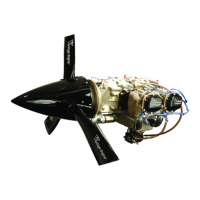
Overhaul Manual
O-360 and IO-360 Series Engines
Installation of Idler Shafts and Gears and
Internal Gear Timing
(1) Install 2 each idler shafts (1, Figure 72-
00-09.20) with 3 bolts (5) and one nut
(10). Torque the bolts (5) and nut (10)
in accordance with the torque
specifications per the Fits and
Clearances section of this manual.
Safety the nuts and bolts with 0.032 in.
safety wire to idler shaft flange holes.
Refer to Figure 72-00-09.21.
WARNING
: PUT ON SAFETY GOGGLES
WHEN INSTALLING OR REMOVING SAFETY
WIRE.
(2) Inspect idler gears and for handling
damage, burrs, and general condition.
WARNING
: LUBRICANTS ARE TOXIC AND
FLAMMABLE. DO NOT BREATHE VAPORS.
BEFORE YOU USE, READ THE MATERIAL
SAFETY DATA SHEET (MSDS) FROM THE
MANUFACTURER OR SUPPLIER. USE IN A
WELL-VENTILATED AREA FREE FROM
SPARKS. WEAR PROTECTIVE GEAR. IN
CASE OF EYE CONTACT, FLUSH WITH
WATER FOR 15 MINUTES AND SEEK
MEDICAL ATTENTION. IN CASE OF SKIN
CONTACT, WASH WITH SOAP AND WATER.
(3) Apply pre-lube oil to idler shafts (1) and
gear bushing (25).
(4) Highlight with a marker the timing
marks on the camshaft, crank gear, and
fuel pump drive idler gear (15).
(5) Place the left-hand idler gear (fuel
pump drive idler gear) over the left idler
shaft aligning its timing marks with the
corresponding timing marks on cam
and crank. Rotate cam and crank as
needed to align with marks on the idler
gear. See Figure 72-00-09.22.
(6) Install the right hand idler gear (20) on
the right side idler shaft.
NOTE:
It is not necessary to align timing
marks on this gear.
(7) Check gear backlash of both idler gears
with feeler gauge or dial indicator.
Backlash limits must be within limits
specified in Fits and Clearances section
of this manual.
(8) Install tachometer shaft assembly (15,
Figure 72-00-09.8) with retaining ring
(25) in camshaft (5) at gear end.
- STOP -
PERFORM IN-PROCESS QUALITY
INSPECTION #2. REFER TO APPENDIX A.
Cleaning, Inspection, and Installation of
Hydraulic Plunger and Cup Assembly
(1) Visually inspect and clean hydraulic
plunger assemblies (25, Figure 72-00-
09.15) with fast dry solvent.
WARNING
: SOLVENT IS TOXIC. USE IN
WELL-VENTILATED AREA. PREVENT EYE
AND SKIN CONTACT AND DO NOT
BREATHE VAPORS. IN CASE OF EYE
CONTACT, FLUSH WITH WATER FOR 15
MINUTES AND SEEK MEDICAL ATTENTION.
IN CASE OF SKIN CONTACT, WASH WITH
SOAP AND WATER.
(2) Depress hydraulic plunger piston with
thumb to ensure proper spring action.
(a) If unit does not compress, use blunt
end of a 3/32 in. diameter rod to
dislodge check ball allowing trapped
air, oil, or solvent to escape.
(b) Remove rod and try depressing
piston again.
WARNING
: LUBRICANTS ARE TOXIC AND
FLAMMABLE. DO NOT BREATHE VAPORS.
BEFORE YOU USE, READ THE MATERIAL
SAFETY DATA SHEET (MSDS) FROM THE
MANUFACTURER OR SUPPLIER. USE IN A
WELL-VENTILATED AREA FREE FROM
SPARKS. WEAR PROTECTIVE GEAR. IN
CASE OF EYE CONTACT, FLUSH WITH
WATER FOR 15 MINUTES AND SEEK
MEDICAL ATTENTION. IN CASE OF SKIN
CONTACT, WASH WITH SOAP AND WATER.
(3) Apply a light coat of pre-lube oil to the
OD of each plunger.
(4) Insert plunger, small tube end first, into
tappet body in crankcase. Refer to
Figure 72-00-09.15.
(5) Insert tappet cup or socket (30) into
tappet body on top of plunger assembly.
28
© March 2005 Superior Air Parts Inc.
72-00-09
Engine Assembly

 Loading...