Overhaul Manual
O-360 and IO-360 Series Engines
Engine Components General Description
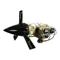
The O-360 and IO-360 series engines are air-
cooled, four cylinder, horizontally opposed,
direct drive engines. See Table 02-00-00.1 for
Manufacturer’s General Specifications.
The complete engine includes the following
components and assemblies:
Crankcase Assembly
Crankshaft Assembly
Camshaft Assembly
Valve Train Assembly
Cylinder Assemblies
Connecting Rod Assemblies
Oil Sump Assembly
Intercylinder Baffles
Starter
Lubrication System (Includes Oil Filter)
Accessory Drive
Ignition System (Includes Spark Plugs)
Fuel System
Starter Support Assembly
Oil Gage
Induction System
Accessories
NOTE: Complete engine does not include outer
cylinder baffles, propeller governor, and airframe
to engine control cables, attaching hardware,
hose clamps, vacuum pump, exhaust system, or
fittings. Fuel pump is included, unless otherwise
specified, on carbureted engines. Alternator
may be included, if specified.
Specifications
The manufacturer’s physical specifications are
listed in Table 02-00-00.2 and are applicable to
the O-360 and IO-360 series engines.
Accessory Drive Specifications are provided in
Table 02-00-00.2 and is also applicable for both
O-360 and IO-360 models. Table 02-00-00.3
lists Physical Specifications for the engines and
Accessories are provided in Table 02-00-00.4.
The Model Specification Data (MSD) provides
more specific information by engine type and is
available from Superior Air Parts, Inc.
Illustrated views of the O-360 and IO-360
engines identifying key components and sub-
assemblies are provided in Figures 02-00-00.1
thru 02-00-00.9 of this section and are listed
Table 02-00-00.5 for convenience. Figure 02-
00-00.10 illustrates the engine wiring diagram
and Figure 02-00-00.11 illustrates the oil system
schematic.
Table 02-00-00.1 • Manufacturer’s General Specifications
Model O-360 and IO-360
Rated Power Hp 180
Rated Speed, RPM RPM 2700
Bore, inches In 5.125
Stroke, inches In 4.375
Displacement cubic inches In
3
361.0
Compression Ratio 8.5:1
Firing Order 1-3-2-4
Spark timing °BTDC 25
Propeller drive ratio 1:1
Propeller drive rotation
(viewed from rear)
Clockwise
3
© March 2005 Superior Air Parts Inc.
02-00-00
Description and Operation

 Loading...