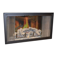
Step
1.
Attach the completed surround with
trim to
theGas Insert. Modei '1-3821 haseight
(8)
predrilled holes, four
(4)
per side at top and
bottom, to accept the surround. Using the
screwsprovided
withthe Gas Insert, securethe
surround to the sides of the Gas insert (figure
42).
For aiignment purposes, do not tighten
screws all the way.
Figure
42
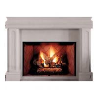
Step
2.
Push In on the surround till it is flush
against the front face of the Gas Insert and the
masonry fireplace.
Centeras needed by sliding
left and right, then tighten screws.
Gas Conversion Kits
WARNING: THE CONVERSION KIT IS TO
BE INSTALLED BY AN AUTHORIZED
OIS-
TRIBUTOR OR OTHER FACTORY CERTI-
FIE0 SERVICE TECHNICIAN IN ACCOR-
DANCE
WlTH THE MANUFACTURER'S
INSTRUCTIONS
ANO
ALL
CODES
AND
REQUIREMENTS OF THE AUTHORITY
HAVING JURISDICTION. FAILURE TO
FOLLOW THESE INSTRUCTIONS COULD
RESULT IN SERIOUS INJURY OR PROP-
ERTY DAMAGE. THE QUALIFIED AGENCY
PERFORMINGTHIS WORKASSUMES RE-
SPONSIBILITY FOR
THIS CONVERSION.
In Canada
I
THE CONVERSION SHALL
BE
CARRIED OUT
IN ACCORDANCE
WlTH THE REQUIREMENTS
OF THE PROVINCIAL AUTHORITIES HAVING
JURlSOlCTlON AN0 IN ACCORDANCE WITH
THE REQUIREMENTS
OF
THE CAN1-6149.1
AND
.2
INSTALLATION CODE.
Gzs
GG;,;ai$;c;;
;d;;l;L;e
t2
z<;;;
,,G"7
Gas insert from the lise of one type of gas to the
useof another. These kits contain ailthe neces-
sary components needed to complete the task
includinq labeling that must be affixed to en-
suresafeoperation. Kit part numbers are l~sted
below and the following steps detailthe conver-
sion procedure
Conversion Kits
-
3"
and
2"
Venting
SFC
PIN
064125
-
Natural to Propane
SFC
PIN
066067
-
Propane to Natural
Conversion Kits
-
4"
and
6"
Venting
SFC PIN 064129 -Natural to Propane
SFC
PIN
064126 -Propane to Natural
Step
1
.Turn olfthe
ga~s~pplyt~theapplian~e.
Remove the front glass door frame from the
appliance. Open the lower controi compart-
ment door.
Step
2.
Carefully remove the top twigs, then
remove the main logs. Exercise care as not to
break logs. Gather, remove and retain any
ember material on the
floor of the appliance.
Step
3.
Refer to page
6
of this manual and
remove the burner assembly and firebox bot-
tom plate.
Slep
4.
Modify the valve by replacing the
pressure regulator
head!olluwing the instruc-
tions provided with the kit
(figore
43
).
Millivol: Valve
Figure
43
steps. Unscrewthe orificesfrom the manifold
outlets and replace them with the ones pro-
vided with the kit. See tables on page 11 and
Figure
28.
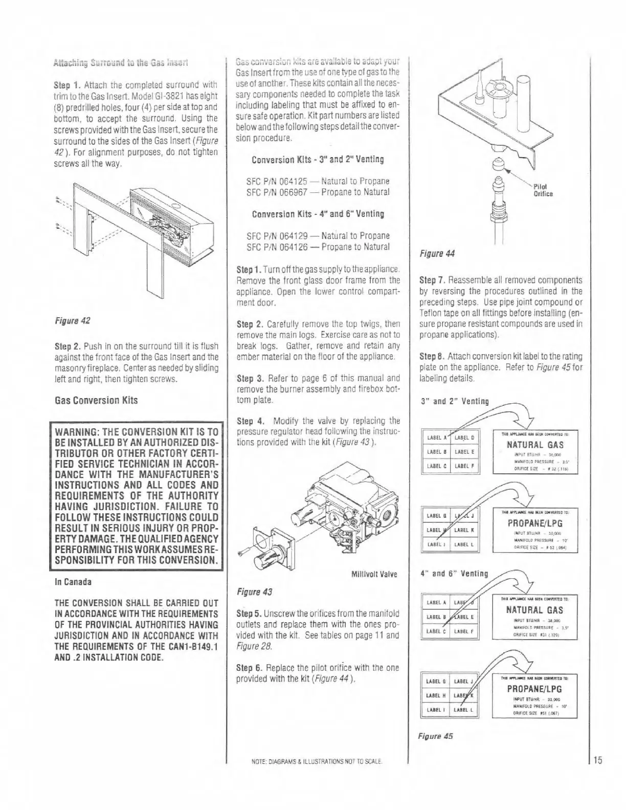
Figure
44
Step
7.
Reassemble all removed components
by reversing the procedures outlined in the
preceding steps. Use pipe joint compound or
Teflon tape on all firtlngs before installing (en-
sure propane resistant compounds are used in
propane applications).
Step
8.
Anachconversion kit label tothe rating
plate on the appliance. Refer to Figure
45for
iabeling details.
3"
and
2"
Venting
,,
PRDPAHYLPG
,"*,,3,&,"*
~
urn
U*loL"
W'IUU.I
tv
OO>F#CE
$RE
-
'
32,
w,
ii
an;;jr
,
UBEL
A
LA8
ms
m-
",,
.,.
c-orm
LLBEL
B
mrt
r
NATURAL GAS
,mu7
b,","n
~
,am
UIL
C
ildtl
*
i
U**"LI
,nnua,
.
3.3.
Ls,,lcl
iiii
n,
,
i*,
Step
6.
Replace the pilot orifice with the one
provided with the kit (Figure
44).
v--~~~~~~~~
PROPANElLPG
IWU1
I,Y*/.
3s.m
NOTE
OIAGVAMS
&
ILLUSlRATiONS NOT
TO
%ALE
I