NOTE: DIAGRAMS & ILLUSTRATIONS ARE NOT TO SCALE.
9
Figure 8
FRAMING SPECIFICATIONS
Figure 9
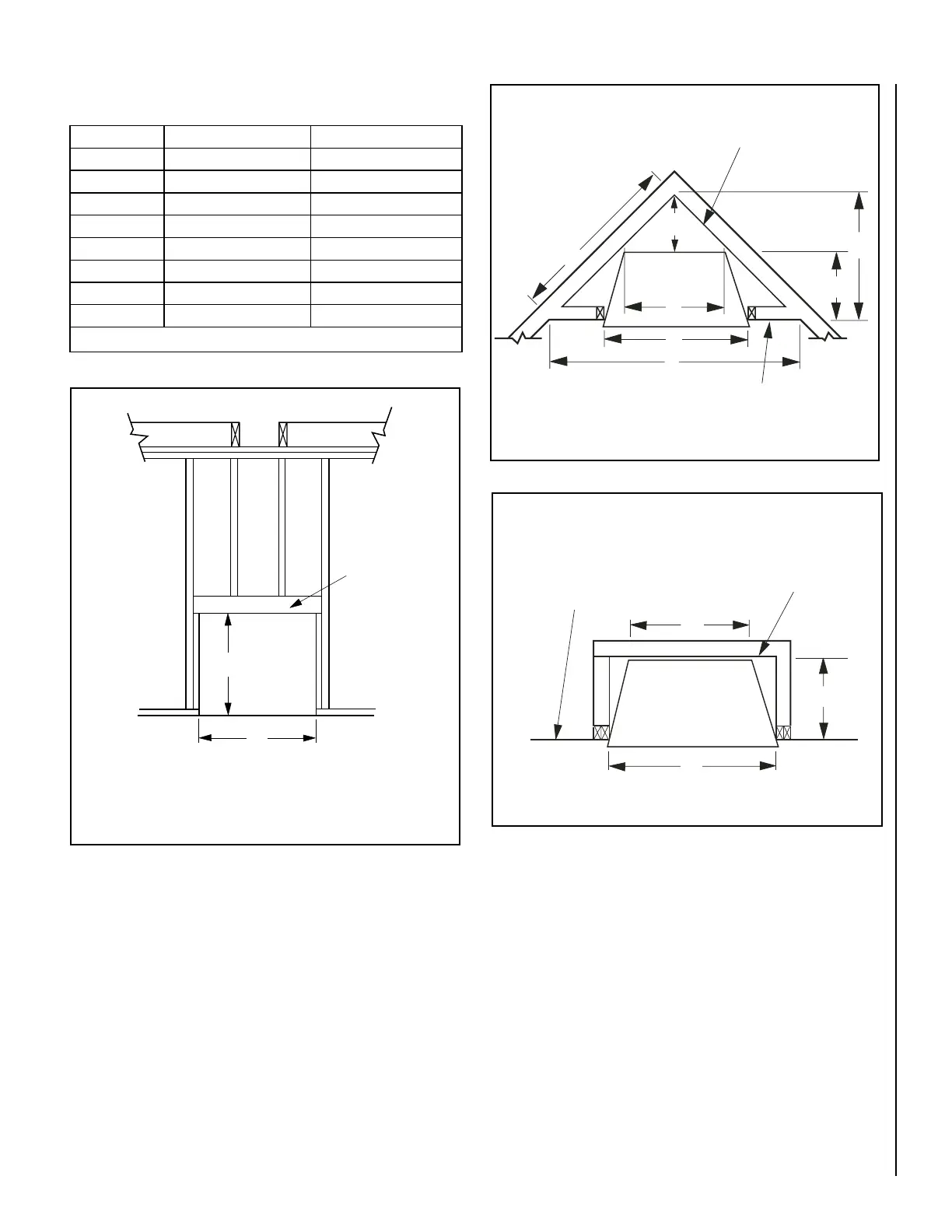
Figure 10
Figures 8, 9 and 10 Correspond To Table 5.
Header
A
B*
* Increase Framing Height By 3/4”
When Using Optional Drain Pan
Corner
Installation
A
C
D
H
F
G
E
Back Wall Of
Chase/Enclosure
Including Finishing
Materials If Any
Rough Framing Face
(Unfinished Shown)
C
G
A
Parallel Installation
Rough Framing Face
(Unfinished Shown)
Back Wall Of
Chase/Enclosure
Including Finished
Materials - If Any
Opening VRE4336 VRE4342
A 42-3/4" (1086) 48-3/4" (1238)
B 46-1/2" (1181) 46-1/2" (1181)
C 23-5/8" (600) 29-5/8" (753)
D 11-1/4" (286) 14-1/4" (362)
E 63-1/2" (1613) 69-1/2" (1765)
F 31-3/4" (807) 34-3/4" (883)
G 20-1/2"( 521) 20-1/2"( 521)
H 44-1/4" (1124) 49-1/8" (1248)
Table 5 - This Table Corresponds To Figures 8, 9 and 10