NOTE:DIAGRAMS&ILLUSTRATIONARENOTTOSCALE.
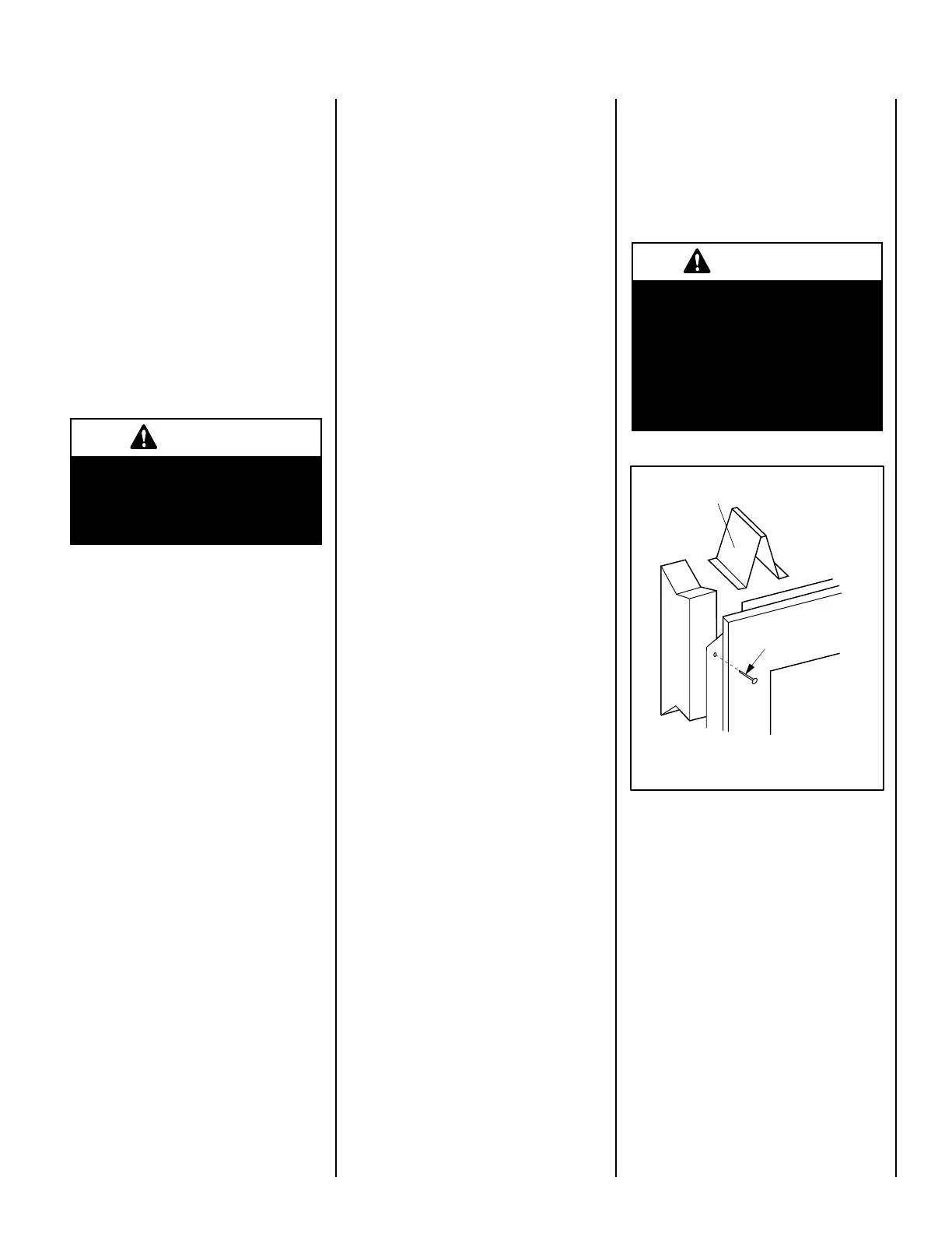
Figure 7
8d Nail or equivalent
nail or screw
9
The reboxmay bepositioned and thenthe
framing built around it, or the framing may
beconstructedandthereboxpositionedinto
the opening.
Usually, no special floor support is needed for
therebox,however,tobecertain:
1.Estimate the total weight of the rebox
system and surround materials such as
marble, brick, stone, etc., to be installed
(see Product Referance Table on Page 10
for appliance weight).
2.Measure the square footage of the oor
space to be occupied by the system and
surrounds.
3.Notetheoorconstruction,i.e.2"x6",2"x
8"or2"x10",singleordoublejoists,type
and thickness of floor boards.
4. Use this information and consult your lo-
cal building code to determine if you need
additional support.
Ifyouplantoraisetherebox,buildtheplat-
formassemblythenpositionreboxontop.
Secure the platform to the floor to prevent
possible shifting.
Firebox Installation
Step 1. Frame these appliances as illustrated in
Figures 9 through 11. All framing details must
allow for a minimum clearance to combustible
framing members as shown in Figures 2
through 6. Also refertoappliancespecications
on Page 10 . Headersmaybeindirectcontact
with the appliance top spacers but must not
besupportedbythemornotchedtotaround
them. All construction above the appliance must
be self supporting, DO NOT USE THE APPLI-
ANCE FOR STRUCTURAL SUPPORT.
Note: The framed depth from a framed wall,
must always be measured from a finished
surface. If a wall covering such as drywall is
to be attached to the rear wall, then the depth
must be measured from the drywall surface. It
is important that this dimension be exact.
Step 2.Levelthereboxbycheckingthetop
edgeoftherebox.Shimifnecessary.
Step 3. Fireplace should be secured to side
framing members using the full length nailing
tabsatthetopandbottomofthereplacefront
face. Use 8d nails (see Figure 7).
Firebox Framing
Construct rebox framing following Figures
9 through 11 and Table 1 on Page 11 for
yourspecicinstallationrequirements.Referto
Figure 8 on Page 10forreboxdimensions.
The rebox may be installed directly on a
combustible floor or raised on a platform of
an appropriate height.Whentheapplianceis
installed directly on carpeting, vinyl tile or other
combustible material, other than wood ἀflooring,
the appliance shall be installed on a metal or
woodpanelextendingthefullwidthanddepth
oftheappliance.Besurereboxrestsonasolid
continuous floor or platform with appropriate
framing for support and so that no cold air can
enterroomfromundertherebox.
Note: The nailing flange and the area directly
behind the nailing flange is exempt from the
clearances described on the firebox clearance
label.
Step 4. To safely operate the heater with con-
sideration of the mantel clearances the hood
mustbeinstalled(ModelVRT2536WSOnly).
CAUTION
Do not block the heat-circulating
air inlets and outlets on these
fireboxes. Doing so may create a
potential fire hazard.
IMPORTANT
Under no circumstances shall the
firebox top spacers be removed or
modified (see Figure 8). The header
may be in direct contact with the top
spacers but must not be supported
by them, notched or altered to fit
around them.