Version V1.3
1. Connect the line as shown above to start the controller. First press and hold "Chip CHIP" and then press the
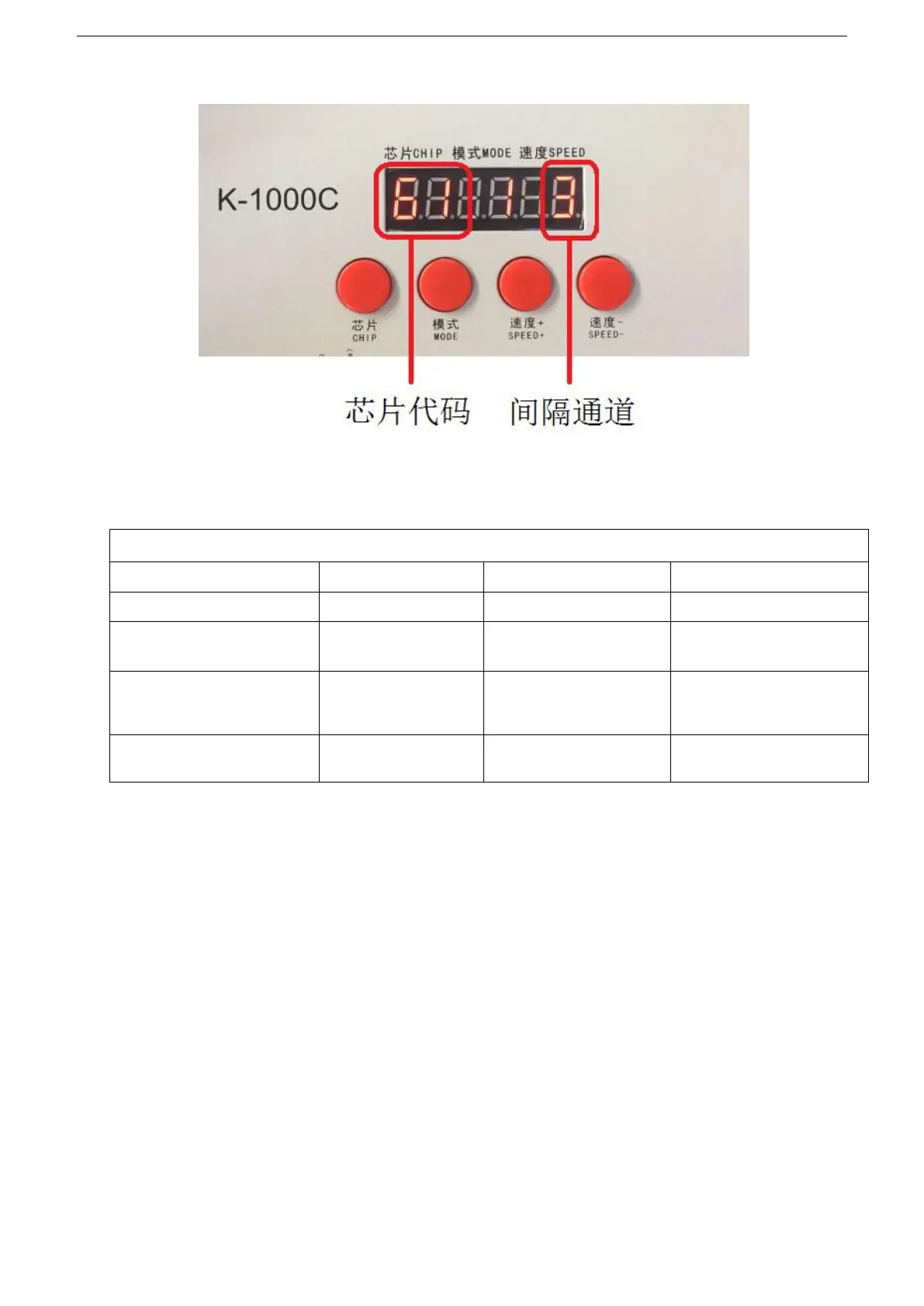
"Mode MODE" button to switch to the address mode, as shown below: "61_*_3",
2. Press the “Chip CHIP” button to select the DMX512 onboard IC model; “Speed+” and “Speed-” select the
fixture interval channel (0-99).
DMX512IC code as the below list:
Appendix: DMX512IC code and IC correspondence table
61: UCS512A*/B*,TM512AL1/AB
69: UCS512E ( Chip parameter
setting)
74: SM17500 regular
address writing
75: SM17500 chip itself
parameter setting
76: SM17500 chip parameter
setting and then address
writing
77: GS8512 regular address
writing
78: GS8512 write single
address
79: GS8512 set as no address
NOTE 1:69 is the chip itself parameter setting for UCS512E* lights, and apply it to the load IC of UCS512E*.
Step 1: select 69 and writ the chip itselt parameter to the same specification lights; Step 2, select
68 to write address for the lights.
NOTE 2: 75: It is the chip itself parameter setting for SM17500 lights, and apply it to the load IC of SM17500.
Step 1: select 75 and writ the chip itselt parameter to the same specification lights; Step 2, select 76
to write address for the lights.
NOTE 3:78:GS8512 write single address, and apply to the load IC of GS8512, at the same time to write the
same address code for multiple lights.
NOTE 4
:
79
:
GS8512 set as no address mode, apply to the load IC of GS8512, Set it to use in serial (TTL/SPI)
mode.
3. After selecting the code, press
“
MODE MODE
”
to write code. At this time, the screen will display A A A. The
following picture is displayed:
 Loading...