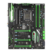
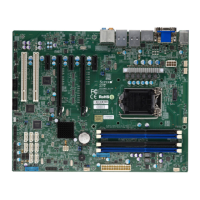
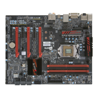
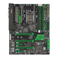
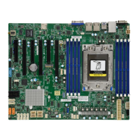
참고
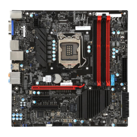
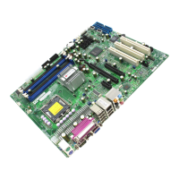
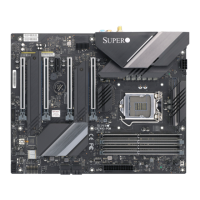
• 본 퀵 레퍼런스 가이드에 사용된 이미지은 예시용일 뿐입니다. 실제 부품은 본 가이드
에 있는 그림과 정확하게 일치하지 않을 수도 있습니다.
• 점퍼, 커넥터, LED 표시등, 메모리 지원 및 CPU/마더보드 설치에 대한 자세한 설명은
사용 설명서의 제2장을 참조하십시오.
MNL-1913-QRG-100
© 2017 Supermicro Computer Inc. All rights reserved. Reproduction of this document whether in part or in whole is strictly prohibited without
Supermicro's written consent. All Trademarks are property of their respective entities. All information provided is deemed accurate at the time
of printing; however, it is not guaranteed.
X
X
A. PS/2 키보드/마우스 포트 F. DVI 포트 K. 기가비트 이더넷 RJ45 LAN 포트 P. S/PDIF 출력
B. USB 2.0 포트 0 G. USB 3.0 포트 6 L. USB 3.1 포트 10 Q. 라인 입력
C. USB 2.0 포트 1 H. USB 3.0 포트 7 M. USB 3.1 포트 11(Type C) R. 라인 출력
D. 디스플레이 포트 1.2 I. USB 3.0 포트 8 N. Center/LFE 출력 S. 마이크 입력
E. HDMI 1.4 포트 J. USB 3.0 포트 9 O. 서라운드 출력
A
B
C
D
E
F
G
H
I
J
K
L
S
M
N
O
P
Q
R
Power Button
Overheat/
Fan Fail LED (-)
 Loading...
