Do you have a question about the Supermicro X10DRH-CT and is the answer not in the manual?
Describes the X10DRH-C/CT/i/iT motherboard's capabilities and target applications.
Outlines the manual's structure, including chapters and appendices.
Explains symbols and conventions used throughout the document.
Provides contact information for Supermicro headquarters and regional offices.
Introduces the motherboard and lists the items included in the retail box.
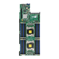
Visual diagram identifying key components and connectors on the motherboard.
Details CPU support, including processor type and QPI links.
Describes memory support, capacity, and module types (LRDIMM/RDIMM).
Details SATA/SAS connection specifications and types.
Covers onboard voltage monitoring and overheat detection.
Lists system management features like UID and SuperDoctor 5.
Details the capabilities of the Intel C612 PCH, including SMBus support.
Discusses system temperature monitoring and CPU cooling.
Crucial warning regarding required 24-pin and 8-pin power connectors.
Details Intel Intelligent Power Node Manager features for power management.
General safety warnings for installation procedures.
Discusses dangers and precautions for battery replacement.
Safety measures for handling static-sensitive components.
Important cautions to avoid damage during motherboard installation.
Step-by-step guide for physically installing the motherboard into the chassis.
Critical warning regarding proper CPU and heatsink installation.
Detailed procedure for installing the LGA2011 processor into the socket.
Step-by-step guide for installing and removing DIMM memory modules.
Guidelines for populating memory modules for optimal system performance.
Step-by-step instructions for installing the CacheVault kit.
Lists and defines the locations and functions of rear I/O ports.
Details different USB port types and their pin assignments.
Explains the function of the Unit Identifier switch and LEDs.
Shows the pin layout for front panel connectors like power and reset.
Details the ATX 24-pin and CPU 8-pin power connectors.
Configures Gigabit and 10G LAN port enablement via jumper.
Procedure to clear CMOS settings using the JBT1 jumper.
Describes the status and activity LEDs for Gigabit LAN ports.
Indicates system power status via the LE2 LED.
Details the SATA 3.0 and S-SATA 3.0 port configurations.
General steps to diagnose and resolve system issues.
Steps to resolve problems preventing the system from booting.
Troubleshooting steps for memory-related errors and issues.
Information needed and steps to take before contacting technical support.
Step-by-step instructions for removing the onboard battery.
Overview of the AMI BIOS setup utility and navigation.
Instructions on how to enter the BIOS setup utility.
How to configure the system date and time within the BIOS.
Settings for processor configuration, including cores and threading.
BIOS settings for CPU P-states and frequency adjustments.
Configuration settings for the Intel I/O Controller.
Enables or disables Option ROM support for PCIe devices.
Sets the operating mode for SATA controllers (IDE, AHCI, RAID).
Sets the operating mode for sSATA controllers (IDE, AHCI, RAID).
Displays and allows configuration of general Management Engine settings.
Procedure to set the BIOS administrator password.
Procedure to set the BIOS user password.
Selects the system boot mode (Legacy, UEFI, Dual).
Sets the priority order for bootable devices.
Saves configuration changes and reboots the system.
Explains POST beep codes for diagnosing system errors.
Guide to installing drivers and utilities from Supermicro.
Instructions for installing the SuperDoctor5 hardware monitoring program.
Explains the Unified Extensible Firmware Interface (UEFI) and its role.
Procedure for recovering the main BIOS block using a USB device.
| Brand | Supermicro |
|---|---|
| Model | X10DRH-CT |
| Category | Motherboard |
| Language | English |