2-3
Safety Information and Technical Specifi cations
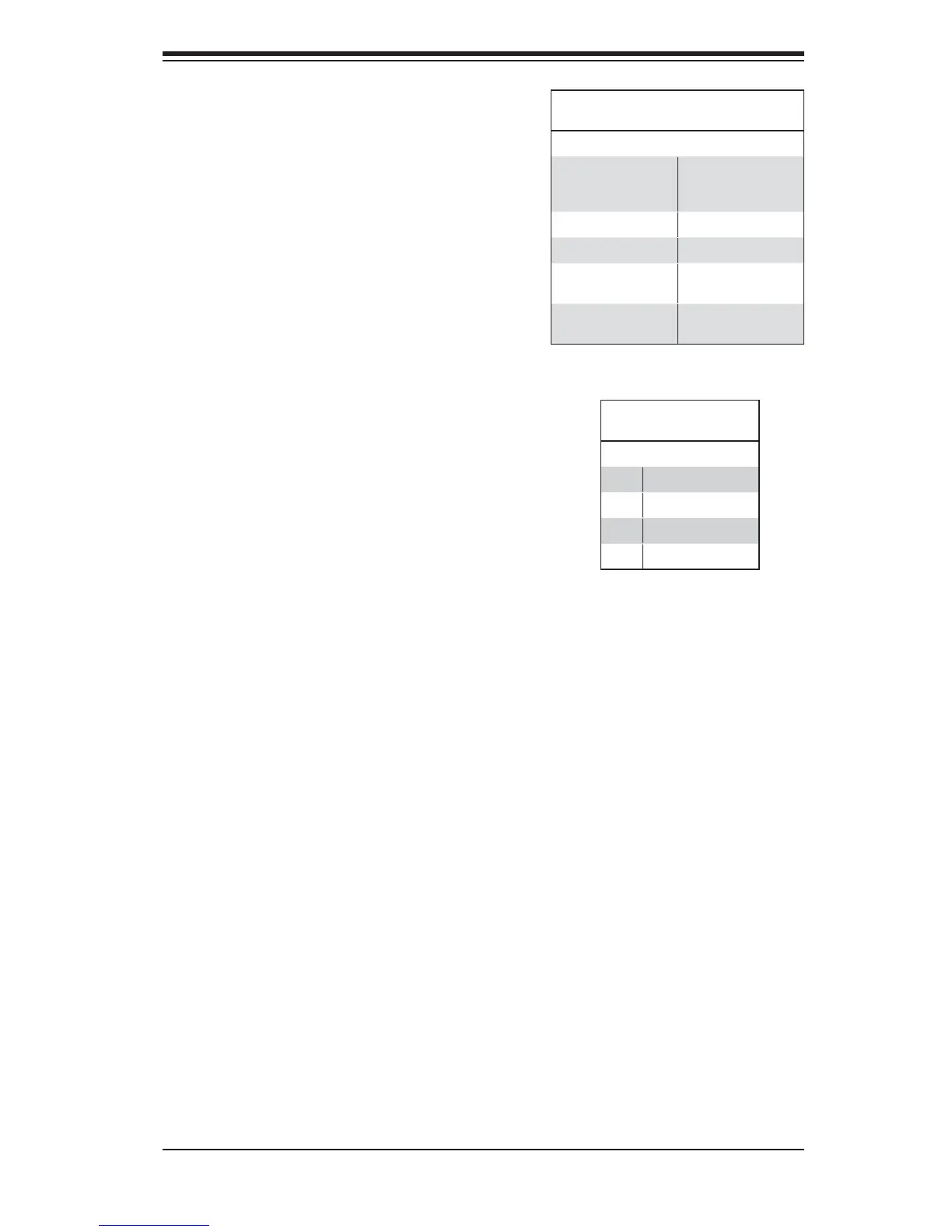
#6. and #7. Sideband Headers
The sideband headers are designated JP51
and JP52. For SES-2 to work properly, you
must connect an 10-pin sideband cable.
See the table to the right for pin defi ni-
tions.
Sideband Headers
Pin # Defi nition Pin # Defi nition
2 Backplane
Addressing
(SB5)
1 Controller
ID (SB6)
4 Reset (SB4) 3 GND (SB2)
6 GND (SB3) 5 SDA (SB1)
8 Backplane
ID (SB7)
7 SCL (SB0)
10 No Connec-
tion
9 No Connec-
tion
#8. and #9. I
2
C Connectors
The I
2
C Connectors, designated JP44 and
JP45, are used to monitor HDD activity and
status. See the table on the right for pin
defi nitions.
I
2
C Connector
Pin Defi nitions
Pin# Defi nition
1 Data
2 Ground
3 Clock
4 No Connection
#10. - #17. SAS Ports
The SAS ports are used to connect the SAS
drive cables. The 8 ports are designated
#0 - #7. Each port is also compatible with
SATA drives. However, do NOT mix SAS
and SATA drives in the same enclosure.

 Loading...


