Do you have a question about the Supermicro SuperServer 2029BT-HTR and is the answer not in the manual?
Provides a brief outline of the functions and features of the SuperServer.
Guides on inspecting the server shipment and selecting a suitable installation location.
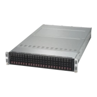
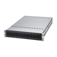
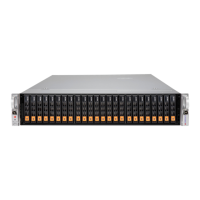
Details the main system features of the 2029BT-Hxxx server, including motherboard, chassis, and CPU.
Details the four control panels on the chassis front for power and status monitoring.
Describes access to storage drives and control panels on the chassis front.
Illustrates features on the rear of the chassis including nodes, power supplies, and PCI slots.
Details the rear I/O ports such as VGA, USB, IPMI LAN, and SIOM network slot.
Explains network port options provided by the SIOM card, including speeds and types.
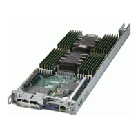
Describes the chassis containing four separate computing node drawers, each with its own motherboard.
Provides a quick reference for motherboard jumpers, connectors, and LEDs with their definitions.
Presents system block diagrams for different server models, illustrating component connections.
Provides advice and instructions for mounting the system in a server rack.
Covers choosing a location, rack, and server precautions, plus mounting considerations.
Details rack rail overview, adjustment, installation, and chassis mounting procedures.
Provides procedures for safely removing power from a node and the entire system before maintenance.
Guides on removing node drawers and chassis covers to access internal components.
Details installation procedures for CPU, heatsinks, memory, and the motherboard battery.
Covers storage drives, carriers, installation, hot-swap, M.2 SSDs, expansion cards, SIOM, and fans.
Details fan headers, TPM header, and other motherboard connectors and their pin definitions.
Illustrates and describes the location and function of the rear I/O ports on the motherboard.
Explains jumper settings for CMOS Clear, VGA, and Management Engine (ME) Recovery.
Describes IPMI LAN LEDs and the BMC Heartbeat LED status indicators.
Guides on installing Windows OS, including RAID configuration and driver loading.
Provides instructions for downloading and installing system drivers and utilities from the Supermicro website.
Describes SuperDoctor 5 software for monitoring system health information like CPU temperature and fan speed.
Introduces IPMI support for remote access, monitoring, and management of the system.
Describes the AMI BIOS setup utility and navigation of its screens.
Explains the Main tab page for setting system date/time and viewing system information.
Covers advanced BIOS settings for boot, power, CPU, and chipset configurations.
Allows configuration of SMBIOS Event Logging, including enabling/disabling and erasing.
Covers system event logging and BMC network configuration settings.
Covers BIOS security settings like administrator/user passwords and secure boot.
Configures boot settings including mode selection, EFI support, and boot order priorities.
Provides options to save/discard BIOS changes and exit the setup utility.
Lists common beep codes and their corresponding error messages during POST.
Mentions additional checkpoint codes and where to find further documentation.
Provides an overview of UEFI and its role as an interface between the OS and firmware.
Explains the recovery BIOS block and how to flash a healthy BIOS image if the main image is corrupted.
Guides on recovering the main BIOS image using a USB-attached device.
Instructions to access the IPMI web interface and check the Event Log for IERR errors.
Details on how to download the crash dump file from the IPMI interface.
Lists requirements and restrictions for enabling Intel VROC, including UEFI boot mode and hardware keys.
Provides links to support information for compatible SSDs and operating systems.
Explains the Intel VROC hardware key function, types, part numbers, and connector.
Step-by-step guide to enable NVMe RAID through UEFI BIOS settings.
Describes the LED indicator on the drive carrier showing RAID status.
Explains hot-plug and hot-unplug for NVMe SSDs under vSphere ESXi.
Identifies the equipment name as "Server" and lists model designations.
Provides a table indicating the presence of restricted substances in various components.
| System bus rate | 10.4 GT/s |
|---|---|
| Processor socket | LGA 3647 (Socket P) |
| Built-in processor | No |
| Motherboard chipset | Intel® C621 |
| Number of processors supported | 2 |
| ECC | Yes |
| Number of DIMM slots | 24 |
| Supported memory types | DDR4-SDRAM |
| Maximum internal memory | 3072 GB |
| Supported RDIMM clock speeds | 2133, 2400, 2666 MHz |
| RAID levels | 0, 1, 5, 10 |
| Storage drive sizes supported | 2.5 \ |
| Number of storage drives supported | 6 |
| Supported storage drive interfaces | Serial ATA III |
| USB 2.0 ports quantity | 0 |
| Ethernet LAN (RJ-45) ports | - |
| PCI Express slots version | 3.0 |
| On-board graphics card model | Aspeed AST2500 |
| BIOS type | AMI |
| BIOS memory size | 32 Mbit |
| Chassis type | Rack (2U) |
| Fan diameter | 80 mm |
| Product color | Black |
| Number of fans | 4 fan(s) |
| Package weight | 38600 g |
| Storage temperature (T-T) | -40 - 60 °C |
| Operating temperature (T-T) | 10 - 35 °C |
| Storage relative humidity (H-H) | 5 - 95 % |
| Operating relative humidity (H-H) | 8 - 90 % |
| Power supply | 2200 W |
| AC input voltage | 100 - 240 V |
| AC input frequency | 50 - 60 Hz |
| Depth | 724 mm |
|---|---|
| Width | 438 mm |
| Height | 88 mm |
| Weight | 24700 g |