53
Chapter 2: Installation
SAN MAC
+
IPMI CODE
BIOS
LICENSE
BAR CODE
MAC CODE
DESIGNED IN USA
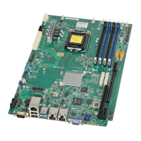
X11SSW-TF
REV:1.01
JPW2
JSTBY1
JSD2 JSD1
JIPMB1
I-SGPIO1
I-SGPIO2
JSXB1C
JSXB1A
JSXB1B
JD1
JBAT1
SP1
JF2
JF1
JUIDB1
LED1
LED3
JL1
JPW1
JPI2C1
I-SATA5
I-SATA0
I-SATA1
I-SATA4
I-SATA3
I-SATA2
JTPM1
JBR1
JWD1
JLED1
JPME2
JPL2
JPL1
JI2C2
JI2C1
JPB1
JPG1
JBT1
DIMMA1
DIMMA2
DIMMB1
DIMMB2
BMC
PCH
JNVME1
LED2
FAN6
FAN5
VGA
FAN4 FAN3
LAN1/2
USB6/7
(3.0)
USB0/1
IPMI_LAN
COM1
FAN2
FAN1
USB9/10(3.0)
USB8(3.0)
USB4/5
USB2/3
COM2
CPU
LAN3/4
LAN1/2
CTRL
LAN3/4
CTRL
J3
M.2 Connection
The X11SSW-TF/-4TF board contains one M.2 NGFF socket 3 connector at J3. M.2 was
formerly Next Generation Form Factor (NGFF) and serves to replace mini PCI-E and mSATA.
M.2 allows for a greater variety of card sizes, increased functionality, and spatial efciency.
The M.2 socket 3 supports 3.0 x4 (32 Gb/s) card in 2260, 2280, and 22110 form factors.
1. M.2 Connector
2. Onboard Power LED Header
1
Onboard Power LED Header
An onboard Power LED header is located at JLED1. This Power LED header is connected to
the Front Control Panel located at JF1 to indicate the status of system power. See the table
below for pin denitions.
Onboard Power LED
Pin Denitions
Pins Denition
1 VCC
2
Connection to
PWR LED on JF1
3
Connection to
PWR LED on JF1
2

 Loading...
